This approach allows for realistic modeling using CAD programs, methods of inconsistent ray tracing through the system for evaluating flares that form glare. In addition, the method allows you to avoid vignetting and minimize aberrations, which is often encountered when using universal attachments, calculated in an arbitrary way without taking into account the design features of the lens with which it is used. The method also makes it possible to correctly design the structure of the camera mount, taking into account the provision of the required position of the attachment, at which the exit and entrance pupils of the optical systems of the lens and the attachment are fully matched.

1. Introduction
An afocal anamorphic (or cylindrical) attachment is an optical system made up of cylindrical lenses, designed to transform images optically by reducing the focal length of the lens. Decrease in focal length is associated with the desired increase in the angular field of view of the lens in a given, usually horizontal, direction. The attachment converts a square to a rectangle or a rectangle with one aspect ratio to a rectangle with a different aspect ratio. For example, to change the aspect ratio of the frame from 4: 3 to 16: 9.
Anamorphic lenses generate a compressed image that is then transformed into a wide-angle image using digital image processing (de-squeezing), implemented in embedded applications.

First of all, anamorphic lens is able to expand the angular field.

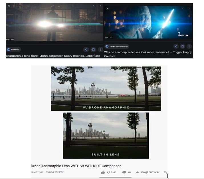
Along with this, the attachment allows you to significantly transform and beautify the shooting made with the camera of smartphones, drones, GoPro cameras and compact digital cameras, creating unique special effects. The effect of expanding the space in the frame is created, the perspective changes, special optical effects appear - lingering glare from bright sources. All this forms a special expressiveness of the transmitted image, surrealism, imitating the effect of shooting with professional expensive and high-quality lenses often used in big cinema. This is due to the special design of the optical system of the attachment.
2. The main optical characteristics of the anamorphic attachment
The attachment is a compact optical system installed in front of the lens, which becomes part of the optical system.
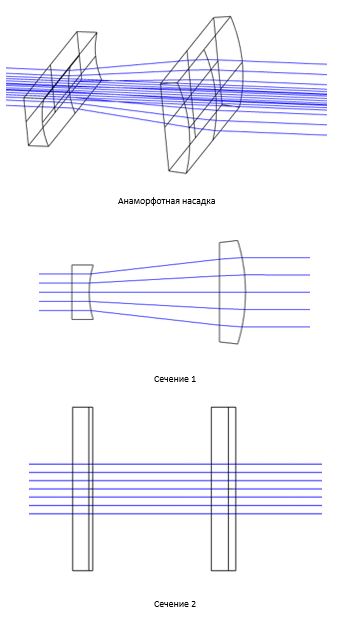
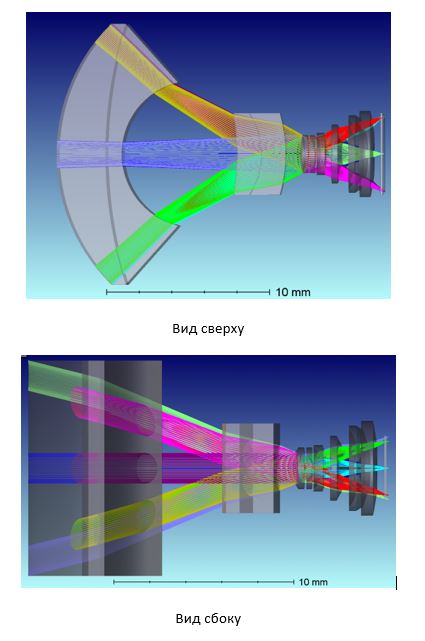
The optical system of the attachment is designed in such a way that in one section, in which the curvature of the cylindrical surfaces is manifested, the attachment acts as a conventional system of spherical lenses, and in the other, perpendicular to it, as a system of plane-parallel plates.
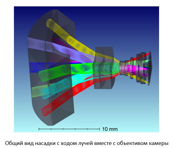
Most attachments have two components. To ensure compactness, a telescopic cylindrical system is used, built in the main section according to the Galileo telescope. It transforms the parallel beams of rays entering it into the same parallel ones at the exit from the system, but with different angles with the optical axis in two mutually perpendicular sections. According to its action, the attachment leads to a change in the focal length of the lens used with it only in one direction, and in the other it works without optical power and without changing the focal length. In Figure 1, they are labeled L1 and L2. For the sake of compactness, the front imaginary focus F1 of the first
negative component L1 coincides with the back focus F'2 of the second L2.
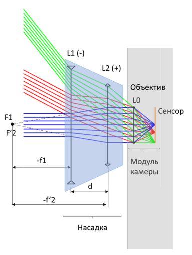
The focal length of a lens with an attachment in the main (horizontal) section is determined by the formula:
where f0 is the focal length of the camera lens, -f1 and f2 are the focal lengths of the first negative and second positive components of the anamorphic attachment. In the main section, the image scale changes in accordance with the apparent magnification of the telescopic system, while in the other section it remains unchanged. This means that the anamorphosis coefficient A of the attachment is equal to the ratio of the absolute values of the focal lengths of the attachment components:
The distance d between the components of the attachment is equal to the difference between the absolute values of the focal lengths of the components:
3. The main stages of designing an optical system
The development of the optical system of a device, such as an afocal attachment, usually consists of the following main steps:
- Determination of the main optical characteristics and dimensional limitations (preparation of technical specifications);
- Dimensional and light energy calculation;
- Aberration calculation or search for the closest prototype;
- Optimization of the optical system using optical software (CodeV, Zemax Optics studio);
- Quality analysis, calculation of tolerances for deviations of design parameters;
Further development usually goes through the following stages:
- Development of the case design (optomechanical design) and the design of attaching the attachment to the smartphone (case or clip);
- Preparation of drawings of optical and mechanical parts and design documentation for the manufacture of the first prototype.
- Prototype manufacturing and testing, changes to the optical system and design. Preparation of design documentation for the manufacture of a prototype 2.
- Prototype manufacturing v.2. Advanced testing with friends, testers, etc. Modernization. Minimization of production costs (cheaper glasses, materials, etc.).
- Development of our own software for image processing (optional).
- Preparation for mass production. Optimization.
- Mass production launched.
- Expansion of the nomenclature.
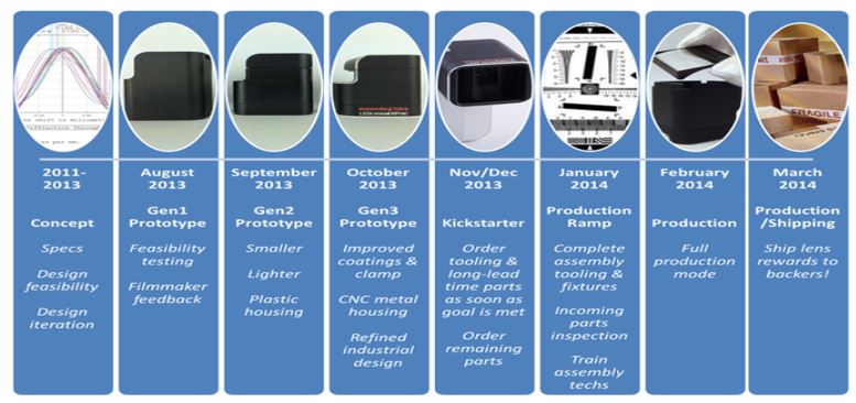
To estimate the time spent on the development life cycle of such a device, the network posted a schedule of one of the startups, which was discussed at the kickstarter.
4. Calculation of the optical system of the anamorphic attachment
Let us dwell in more detail on the first part, devoted to optical design.
Dimensional calculation
An important point at the initial stage of optical design is the availability of design parameters of the main objective, for which the anamorphic attachment is calculated. Often a patent found by a company name can be used as a starting point.
As the initial optical system, we took a system based on a fast F1.8 lens of the front 13-megapixel camera of a smartphone, the optical scheme and design parameters of which are presented below.
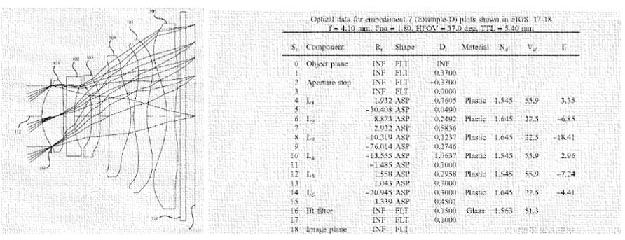
Further, the initial data on the main geometric parameters and design parameters of the system were transferred to the Zemax Optics Studio program, as a result, the system was obtained:

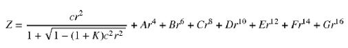
Note that the objective lenses are made of plastic and have a complex aspherical surface shape, representing a higher-order aspheric, described by the second-order deformed aspherical equation using deformation coefficients at even degrees of radial coordinates on the surface:
The main optical characteristics of the camera itself have the following values:
- The focal length of the smartphone camera lens is f'0 = 4.1 mm.
- Relative aperture: ...
- The entrance pupil diameter is mm.
- Entrance Pupil Position: The entrance pupil of the objective is aligned with the aperture diaphragm mounted on the barrel of the first objective lens mm.
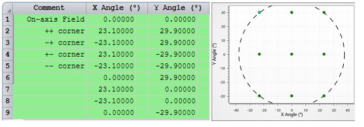
- The field of view of a smartphone camera lens without an attachment is:
- The diagonal full field of view of the lens is 71.2 °.
- Diag=5. 867mm, (aspect ratio): 4:3.
- 13MP. : 1.12 um.
Let us take the value of the coefficient of anamorphosis of the afocal attachment A = 0.67. The anamorphosis ratio determines the horizontal compression ratio of the coordinates in the image. Those. in our case, the horizontal coordinates are compressed by 33%.
Let's set the following values of the focal lengths of the attachment components f1 = -13.4 mm (negative lens), f2 = -f1 / A = 13.4 mm / 0.67 = 20 mm (positive lens), the distance between the attachment components is equal to the sum of the focal lengths of the components: d = f2 + f1 = 20mm + (-13.4) mm = 6.6mm. As a result, the focal length of the [lens] + [attachment] system in one section (vertical) will not change and will be equal to the focal length of the 4.1mm lens, and in the horizontal section the focal length will decrease and become equal to:
The field of view of a lens with an attachment increases in the horizontal plane and is calculated by the formula:
,
where A is the lens anamorphosis coefficient.
As a result:
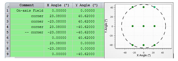
The field of view of a smartphone camera lens with an attachment increases to values:
Next, an aberration calculation and optimization of an optical system consisting of two components is carried out.
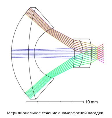
The result is an optical system consisting of two double-lens glued cylindrical components.
The main characteristics of the nozzle:
- Angle of view:
- Diagonal angle of view: 87.53 °.
- Aspect ratio: 16: 9.
- Angle Magnification: ...
- System length along the optical axis: L = 14mm
- Air gap between components: d = 7 mm
- First component aperture size: 16mm x12mm
- : 4
- : 3
5.
An approach to calculating an anamorphic afocal attachment to a compact camera lens is proposed. The nozzle consists of two double-lens cylindrical components glued together. To ensure compactness, a telescopic cylindrical system is used, built in the main section according to the Galileo telescope. The frontal component of the system is short-focus, which has a negative optical power, and the second component has a positive power. In this case, the front imaginary focus of the first component coincides with the back focus of the second component. The exit pupil of the system is located behind the attachment and aligned with the entrance pupil of the compact camera lens. The length of the system does not exceed the maximum transverse dimension of the first component. The glass thickness of the bonded front component lenses does not exceed 30% of the total system length. According to the author,this approach ensures precise matching of the pupils of the system and obtaining high image quality while reducing the size and weight of the nozzle.