Introduction
As is often the case, a database architect needs to develop a database for a specific solution.
One Friday night, on the train home from work, I thought about how I would create a service for hiring employees for different companies. After all, none of the existing services allows you to quickly understand how suitable a candidate is for you. It is not possible to create complex filters that include or exclude a set of specific skills, projects or positions. The most that services usually offer are filters by company and partly by skill.
In this article, I will allow myself to dilute the strict presentation of the material a little by mixing technical information with non-technical examples from life.
To begin with, let's analyze the creation of a database in MS SQL Server for the job search service.
This material can be transferred to another DBMS such as MySQL or PostgreSQL.
Basics of design rules
To design a database schema, you need to remember 7 formal rules and the very concept of normalization and denormalization. They are the basis of all design rules.
Let's describe in more detail 7 formal rules:
- one-to-one relationship:
1.1) with a mandatory connection:
an example can be a citizen and his passport: any citizen must have a passport; one passport for each citizen
This relationship can be implemented in two ways:
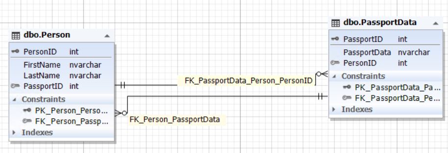
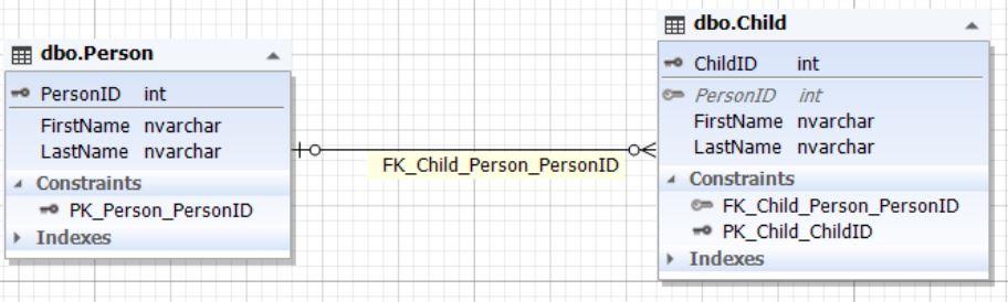
1.1.1) in one entity (table): Fig.1. Citizen entity Here, the Citizen table is a citizen entity, and the PassportData attribute (field) contains all passport data of a citizen and cannot be empty (NOT NULL). 2) in two different entities (tables): Fig. 2. Relationship between Citizen and PassportData entities


Here, the Citizen table is the citizen entity and the PassportData table is the citizen's passport data entity (the passport itself). The citizen entity contains a PassportID attribute (field) that refers to the primary key of the PassportData table. In turn, the passport data entity contains the attribute (field) CitizenID, which refers to the primary key CitizenID of the Citizen table. Citizen table PassportID field cannot be empty (NOT NULL). It is also important to maintain the integrity of the CitizenID field of the PassportData table to ensure a one-to-one relationship. In other words, the PassportID field of the Citizen table and the CitizenID field of the PassportData table must refer to the same records as if it were the same entity (table) presented in clause 1.1.1.
1.2) with an optional link:
an example would be a person with or without a passport for a particular country. In the first case, he will be a citizen of the country in question, and in the second, he will not.
This relationship can be implemented in two ways:
1.2.1) in one entity (table): Fig.3. Person entity The Person table is a person's entity, and the PassportData attribute (field) contains all his passport data and can be empty (NULL). 2) in two entities (tables): Fig. 4. Relationship between Person and PassportData entities

The Person table is the person's entity, and the PassportData table is the person's passport data entity (the passport itself). The human entity contains a PassportID attribute (field) that refers to the primary key of the PassportData table. In turn, the identity of the passport data contains the attribute (field) PersonID, which refers to the primary key PersonID of the Person table. The PassportID field of the Person table can be NULL. It is also important to maintain the integrity of the PersonID field of the PassportData table. This is necessary to ensure one-to-one communication. The PassportID field of the Person table and the PersonID field of the PassportData table must refer to the same records as if it were the same entity (table) shown in clause 1.2.1. Or, these fields must be null, that is, contain NULL.
- :
2.1) :
. .
:
2.1.1) ():
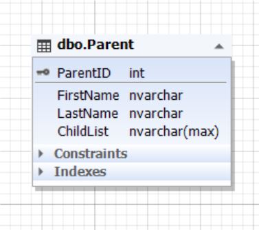
.5. Parent
Parent , () ChildList . (NOT NULL). ChildList (NoSQL) XML, JSON .
2.1.2) ():
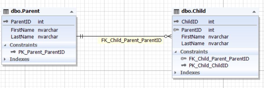
.6. Parent Child
Parent , Child — . Child ParentID, ParentID Parent. ParentID Child (NOT NULL).
2.2) :
, .
:
2.2.1) ():
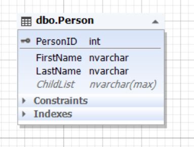
.7. Person
Parent , () ChildList . (NULL). ChildList (NoSQL) XML, JSON .
2.2.2) ():
.8. Person Child
Parent , Child — . Child ParentID, ParentID Parent. ParentID Child (NULL).
2.2.3) , () () :

.9. Person
() Person () ParentID, PersonID Person (NULL).
« » .
- :
. , «» «», , . , , .
- :
: , . , .
, NoSQL, , . , 3 ():
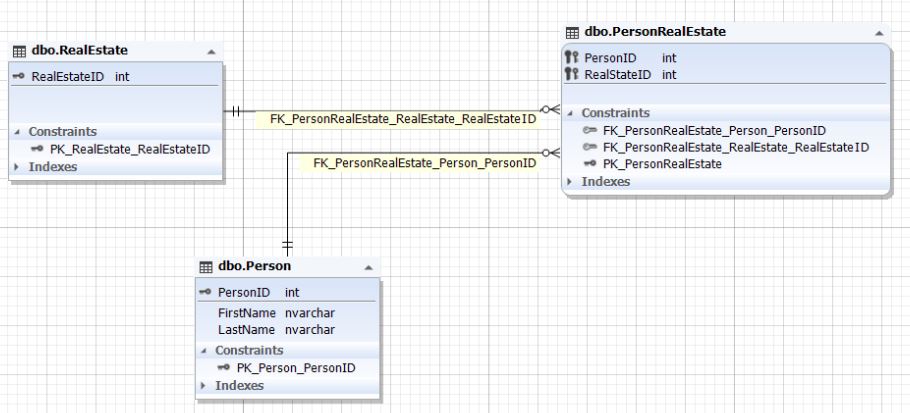
.10. Person RealEstate
Person RealEstate . () () PersonRealEstate. () PersonID RealEstateID PersonID Person RealEstateID RealEstate . , PersonRealEstate (PersonID; RealEstateID) PersonRealEstate.
. , . , 1.1.2 1.2.2.
One-to-many and many-to-one relationships can be implemented through more than two entities. For this, the necessary attributes are added, which refer to the primary keys of the necessary corresponding entities. This implementation is similar to the examples described above in paragraphs 1.1.2 and 1.2.2.
Where are the seven formal rules?
Here they are:
- Clause 1 (Clause 1.1 and Clause 1.2) - the first and second formal rules
- Clause 2 (Clause 2.1 and Clause 2.2) - the third and fourth formal rules
- clause 3 (similar to clause 2) - the fifth and sixth formal rules
- item 4 - seventh formal rule
In the text above, these seven formal rules are grouped into four functional blocks.
When talking about normalization , you need to understand its essence. Normalization leads to a decrease in the repeatability of information storage, and therefore to a decrease in the possibility of anomalies in the data. However, normalization when splitting entities leads to more complex query constructions for data manipulation (insertion, modification, selection and deletion).
The reverse normalization process is called denormalization . This is a simplification of building data access queries due to the aggregation and nesting of entities (for example, as shown above in clauses 2.1.1 and 2.2.1 using incompletely structured data (NoSQL)).
That's the whole point of database design rules.
Are you sure you understand the relationship in seven formal rules? Did you understand, and did not recognize? After all, knowing and understanding are two completely different concepts.
I will explain in more detail. Ask yourself, can you sketch out a database model, albeit enlarged by entities, for any subject area and for any information system in a couple of hours? (subtleties and details can be completed by asking around analysts and customer representatives). If the question surprises you, and you think that this is impossible, then you know the seven formal rules, but do not understand them.
For some reason, many sources ignore the fact that these relationships were not invented, but revealed. They initially exist in the real world both between subjects and between subjects and objects.
Also, this relationship can change, moving fromone to one to one to many , many to one or many to many . The obligation of communication can change or remain unchanged.
Let me tell you about one case when, from the knowledge of the seven formal rules, I came to the understanding of these relations.
At one time, I was embarrassed by the fact that at the university I knew these seven formal rules, but in industrial practice (the university sends students to various companies to gain professional experience) for a very long time I built models of bases for different subject areas. I thought about it and realized that I did not understand this relationship.
Observing people helped me, and the essence of the relationship was revealed in a dream. I will retell this dream in a simplified form: only what allows you to better understand these seven formal rules - without detailing everything else.
The dream was about a family with a father, mother and children. The father dies in a car accident, and the mother begins to drink, and the children are eventually taken to the orphanage. These children are left without parents for a long time. Then some children have guardians, there are several of them too.
Did you trace what kind of relationships were between the subjects, and how these relationships changed?
Let's take a closer look.
- When the family was complete, with several children, the relationship between parents and children was many-to-many .
- , . , , , , .
- .
- — .
- , : , ().
The relationship between husband and wife is one-to-one with a mandatory bond in formal marriage or one-to-one with an optional bond prior to registration. There can be only one wife, just as there can be only one husband. At least in Russia. But in another country, polygamy is possible, and then the relationship between husband and wives will be one to many , and between wives and husband - many to one .
Hopefully you are now much closer to understanding these seven formal rules.
It is worth constantly practicing: observing people and identifying existing relationships both between subjects and between subjects and objects. The above described the citizen and his passport as a one-to-one relationship with a mandatory link... At the same time, an example of a person and his passport is a one-to-one relationship with an optional link .
Having understood the seven formal rules, you can easily design a database model of any complexity for any information system.
You will also see that there are many ways to implement a relationship, and the relationship itself can change. A database model (schema) is a snapshot of relationships between entities at a particular point in time. That is why it is important to determine both the entities themselves - images of objects from the real world or subject area, and their relationship with each other, taking into account changes in the future.
A well-designed database model, taking into account changing relationships in reality or in the domain, will not need to be changed for years or even decades. This is especially important for data warehouses, where changes entail re-saving large amounts of data (from several gigabytes to many terabytes).
It is important to remember that tables in a relational model are entity relationships, and rows (tuples) are instances of these relationships. But to make it easier, tables are often understood as entities, and table rows are entity instances. Their relationship is expressed through relationships in the form of foreign keys.
Designing a Database Schema for Finding Job Applicants
After we covered the basics of database design rules in part one, let's create a database schema for finding job seekers.
To begin with, let's define what is important for employees from the company who are looking for candidates:
- for HR:
1.1) the company where the applicant worked
1.2) the positions previously held by the applicant in these companies
1.3) skills and abilities that the applicant used in work;
as well as the duration of the job of the applicant in each company in each position and the duration of the use of each skill and ability
- for a technical specialist:
2.1) positions held by the applicant in these companies;
2.2) skills and abilities that the applicant used in his work;
2.3) projects in which the applicant participated;
as well as the duration of work of the applicant in each position and in each project, the duration of the use of each skill and ability
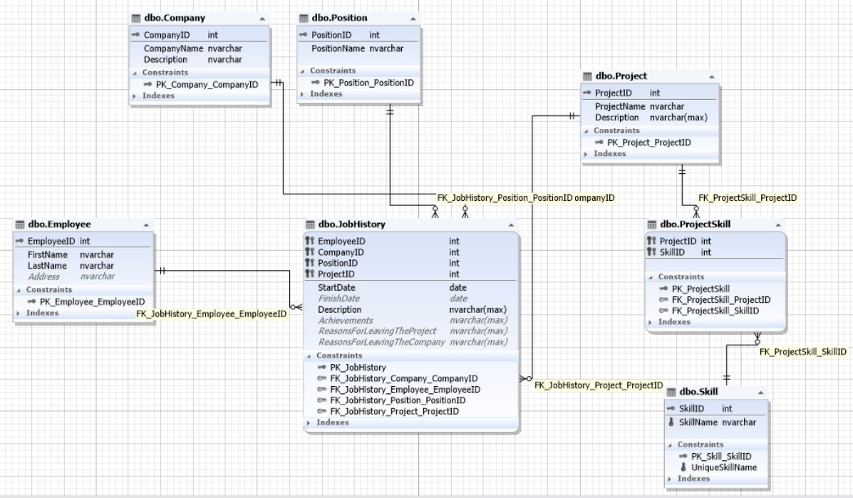
First, let's identify the required entities:
- Employee
- Company
- Position (position)
- Project
- Skill
- Companies and employees are like many to many , since an employee could work in several companies, and many people work for the company.
- Positions and employees are related in a similar way: several employees can occupy one position both within one or several companies.
- , , . , — .
- : .
- , .
- .
Since it is very important to record how long an employee has worked in a particular position in a particular company, as well as on each project, the diagram of our database may be as follows: Fig. 11. Database Schema for Finding Job Applicants Here, the JobHistory table acts as the entity of the job history of each job seeker. That is, it is a resume that introduces a many-to-many relationship between the entities employee, company, position, and project. Projects and skills relate to each other as many to many and therefore communicate with each other through the ProjectSkill entity (table).
When you understand the relationship between subjects and between subjects and objects - the already mentioned seven formal rules - this or a similar scheme can be implemented “on the knee”: on a piece of paper, in less than an hour. And this is also taking into account the fatigue after a fruitful working day.
Here it was possible to simplify the data addition scheme if the “skills” were embedded in the “projects” entity through incompletely structured data (NoSQL) in the form of XML, JSON, or simply list the names of the skills separated by semicolons. But that would make it harder to sample by skill and filter by skill.
A similar model is at the heart of the Geecko project database .
As you can see, there is nothing complicated in the design of information systems in terms of database design. This is just a reflection of objects and subjects from reality, transferred to the "entities" of the database schema. The relationship between these entities is fixed at a certain point in time, taking into account future changes.
What exactly we take from reality and put it into the essence of the scheme, and what relationships we build in the model, will depend on what we want from the information system in general, here and in the future. In other words, what data we want to receive at the current time and after a certain time in the future.
A bit of lyrics
After you put the model into operation, stop for a moment and think: a new little world has just been created. It has its own entities from the real world and its own relationships. Yes, this is a digital world, but it will now develop its own way. He will communicate (integrate) with other systems (worlds), also created according to their own rules. Data will flow in these systems like blood in a living organism.
And before going to bed, think about the fact that the seven formal rules have always been, and that they surround us everywhere. No more and no less, always seven. All relationships in real life can be decomposed into these seven formal rules. And when you think or dream, how do the entities relate to each other - not according to the same seven formal rules?
In general, I am sure that this relationship (seven formal rules) was revealed by a very good psychotherapist, possibly a woman. It was a very long time ago, long before the very concept of information technology appeared. And the most interesting thing is that these relationships live outside the database and IT - the latter only use them to model information systems.
But we got off topic a little. I only urge at the moment of creating a new system to approach this process with a soul. And then believe me, the moment of creation will happen. The system designed in this way will be the most alive of all living beings in the digital world.
Afterword
The diagrams for the examples were implemented using the Database Diagram Tool for SQL Server . However, DBeaver has similar functionality .
Sources
- SQL Database Design Basics with Example
- Geecko
- Microsoft SQL documentation
- SSMS
- Database Diagram Tool for SQL Server