
For an orderly arrangement of copies of objects in a drawing in nanoCAD with the SPDS module, several utilities are proposed:
- Array creation (SPARRAY);
- Array by area (SPARDARRAY);
- Tile layout (SPPLTARRAY);
- Create a custom hatch (SPHPATTERN).
Let's consider the main advantages of each of them.
Array creation
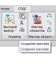
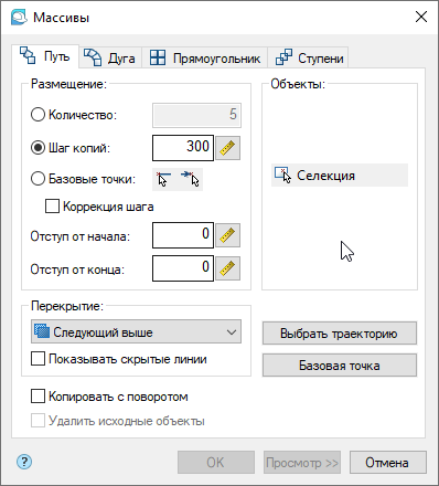
In the ribbon interface, the Create Array (SPARRAY) command is located in the SPDS tab, the Utilities group (Fig. 1). The Create Array command is designed to replicate objects in various ways. In its dialog box (Fig. 2), you can see several tabs:
. 1.
- Path - an array of objects along the path;
- Arc - an array of objects along an arc path;
- Rectangle - a rectangular array of objects;
- Steps are a stepped array of objects.
Each tab has a Selection button . By clicking on it, the user indicates the drawing objects that need to be multiplied.
Depending on the type of array, different replication parameters are set: the number of copies of objects, the distance between objects, indents. There are options that allow you to adjust the rotation of objects, their overlap, etc. After all the parameters have been specified, the View button becomes active in the Arrays tab of the dialog box . In the preview mode, you can exclude some of the objects from the array, or click the Modify button to return to the dialog box of the Create array command and redefine the replication parameters (Fig. 3). Click OK to confirm the array creation
. 2.

. 3.
in the Arrays dialog or in the View Result dialog . The array will be built.
The Create Array command allows you to create copies of objects along a specified path, arc, stepped and rectangular patterns. The presence of the preview function provides the ability to adjust the parameters of replicating objects before displaying graphics on the drawing.
Array by area
To create an array of objects in a closed path, use the Array by Region (SPARDARRAY) command . In the nanoCAD SPDS tape interface, it is located next to the Create array command (see Fig. 1).
The main parameters of replication are set in the command dialog box (Fig. 4). To select objects to copy, click the Object (s) button . The graphic switch allows you to select the required copying method: rhombus, square or triangle (Fig. 5a-c). It is necessary to set the step between adjacent copies (H) , the minimum offset from the center of the copy to the edge of the object (∆)

. 4.

)

)

)
. 5.
and specify the areas to build the array. After entering all the parameters, markers will appear in the array construction area, indicating the centers of the copied objects (Fig. 6). The preview shows the number of copies of the object.

. 6.
Click OK to build the array (Fig. 7).

. 7.
The Array by area command allows you to distribute objects within the area without calculating the number of rows and columns.
Tile layout
Layout of tiles (SPPLTARRAY) is a specialized utility for laying out paving slabs. The most popular types of tiles are included in the SPDS object database and are designed as groups for ease of layout execution (Fig. 8). The user can independently replenish the database.
In the nanoCAD SPDS tape interface, the command is located next to the Create array command (see Fig. 1).
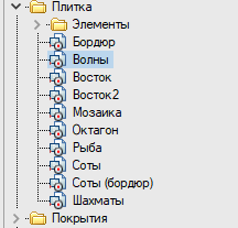
Figure: 8. Paving slabs in the base of SPDS elements.
Order of command execution:
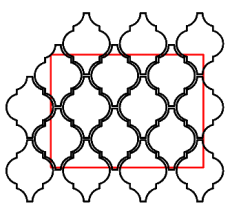
1) Place the tiles in the drawing and draw the layout contour (Fig. 9).

. 9. ()
2) Call the Tile layout command . In the command dialog box, assign the required parameters in sequence (Fig. 10). Click on the Layout Scheme lineand specify the group handle of the inserted tile. Select one of the modes for creating edge tiles (Fig. 11a-d). If you need to make each tile a separate object, turn on the switch of the same name. Set the tile layout area. After entering the required parameters, the OK button will become active . 3) The result of laying out paving slabs is shown in Fig. 12. In our example, the checkbox from the item Make each tile a separate object

. 10.

)
)

)

)
. 11.
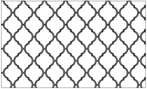
. 12. «»
removed, which means that a single object is created from separate tiles. Object properties will contain information about the number, price and weight of tiles of each type, as well as the total weight (for whole tiles) and cost (Fig. 13). Individual tiles can be removed by right-clicking on them, and the total quantity, weight and cost will be adjusted.
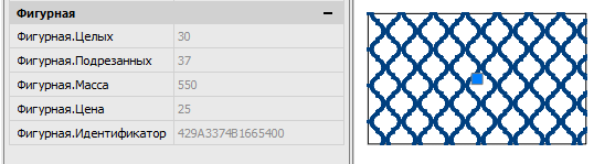
. 13. ,
The Tile Layout utility allows you to "lay" paving slabs as quickly as possible, significantly reduces the time for counting materials and is a tool that simplifies the work on landscaping drawings.
Creating a hatch
Another way to replicate objects is shading. In the SPDS menu of the classic interface, you can find a utility for creating a custom hatch: Creating a hatch (SPHPATTERN). The hatch created with this tool fully accepts the properties of the nanoCAD hatch: associativity, the ability to change the scale, tilt angle, overlay with a closed tolerance. As a result of using this utility, the hatching is written as an independent file with the * pat extension. Remember that this file will be located on the user's computer, and when transferring a drawing containing a custom hatch, the package (ETRANSMIT) should be generated.
Basic rules for drawing a custom fragment to create a hatch:
- a repeating fragment in hatching is performed only by segments, does not contain arcs, splines, etc .;
- each segment of the fragment has its own color;
- the frequency of repetition of the fragment is clearly expressed;
- the sketch must include at least three repeating fragments of the future hatching;
- hatch sketch size - no more than 300x300 mm.
When the sketch is drawn according to the above rules (see Figure 14), call the Create Hatch command , select the hatch fragments and press Enter . In the file save dialog specify the path to the hatch file.

.14
Thus, without having programming skills, the user can create their own hatches and not be limited by the GOST and ISO standards.
Conclusion
The nanoCAD SPDS module has several utilities that allow you to arrange copies of objects by step and number. Depending on the object of replication and the desired result, you can choose the most suitable tool.
Share your experience in domestic CAD, discuss existing functionality and suggest a new one on the nanoCAD forum.
Within 30 days, you can test a worthy alternative to foreign CAD for free. Follow the link and download nanoCAD Pro with the maximum number of modules and capabilities.
Articles related to this:
- Utilities nanoCAD SPDS. Export to file, work with SPDS graphics
- Utilities nanoCAD SPDS. Find and replace text
- Utilities nanoCAD SPDS. Recovering tables and formats
- Additional nanoCAD tools
Tatiana Vaskina,
technical specialist of
Nanosoft JSC