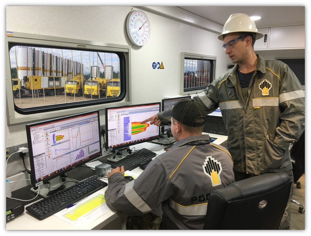
Today we will talk about two special areas where modeling is indispensable, we will tell you how engineers know how to understand the readings of the sensors of pumps, cranes and quadcopters, and finally find out in what units the weight is measured. Any well is an object of capital construction, like a building or a plant, which requires capital investments, planning, periodic and major repairs, and only if these requirements are met, it will be able to return the costs of its construction and bring profit in both energy and monetary terms. ... The life of the well is directly related to the technological workover operations carried out periodically on it. There are operations, such as lowering and lifting and replacing pipes or a pump, which only need a clear plan and the maintenance of safety measures by the repair team.And there are special operations that require deep engineering study and additional modeling, and without these actions the life of the well may simply end. A well, let me remind you, is a big investment of funds and energy.
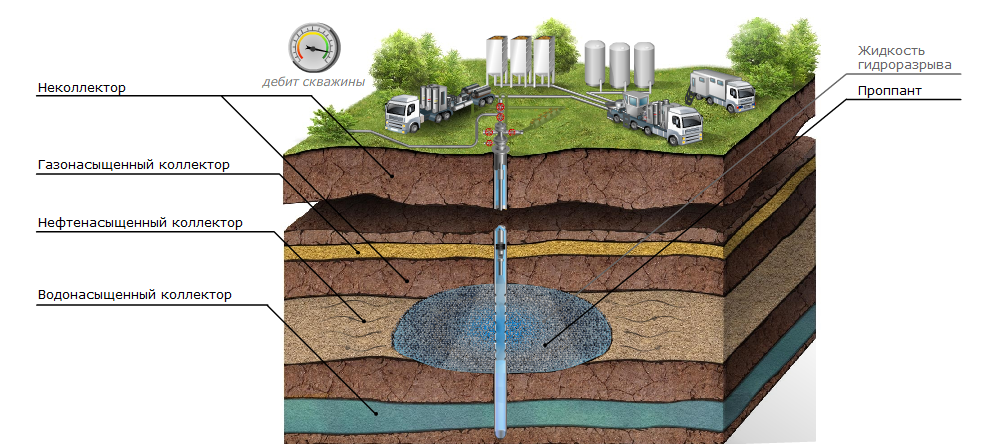
Hydraulic fracturing (hydraulic fracturing) is one of the most important well operations today. The essence of hydraulic fracturing is as follows. A special liquid similar to jelly is pumped into the well under high pressure (up to a thousand atmospheres!) (In fact, this is jelly - a food gelling agent is used in its production). The pressure breaks the formation, pushing the rock layers apart. At the depth where hydraulic fracturing is usually performed, it is easier to move the rock to the sides than upwards, so the fracture is almost flat and vertical, while its width is a few millimeters or centimeters. Then, together with the liquid, proppant begins to be fed (sometimes they also write proppant, with two "p" - and so, and so it is correct) - a mixture of strong ceramic granules, similar to sand, with a diameter from fractions of millimeters to millimeters.The purpose of hydraulic fracturing is to inject the required amount of proppant into the formation (or, more precisely, into the reservoir - into the part of the formation where oil is located) so that a permeable area is formed, connected to the well. The liquid, of course, will leak into the reservoir, and the proppant will remain where it managed to reach. Low-permeability fields (and now almost all new fields are just such, all large good traditional fields have long been found and drilled out) it is useless to drill with conventional wells: the permeability is low, and oil barely oozes to a small wellbore. It is, of course, theoretically possible to drill a very thick well so that its wall area is large, but it is obvious that in practice this is unrealistic. But if hydraulic fracturing is done on the well, then an extensive fracture with a large wall area well connected to the well is formed around the well.Oil seeps out as slowly as before, but now the well is collecting it slowly from a large area, and the total production rate is good, and the well is economically justified. To further increase the area from which oil is collected by one well, the wells are drilled horizontally, and hydraulic fracturing is carried out several times - in different places of the horizontal wellbore.
What can go wrong here, and why do you need modeling? Firstly, the crack may go in the wrong place, and the proppant may not be distributed over it as we would like. The field could have been developed for a long time, and some of the rock layers were already "watered", saturated with water, and, possibly, from the very beginning at the deposit, the lower layers were saturated. If suddenly a crack passes from a well to water-saturated or gas-saturated formations and is filled with proppant, then instead of part of the oil, the well will produce water or gas.
Secondly, the proppant can get stuck at the entrance to the fracture, because the liquid in which it is mixed turned out to be too low viscosity, or the permeability of the formation turned out to be higher than you planned, and the liquid will simply leak quickly, leaving a solid proppant, which, of course, is refuses to move without liquid. Then the entire well will be filled with proppant, and additional flushing costs will be required to clean it.
Finally, thirdly, the proppant can "pump" beyond the wellbore and lose contact with it. Then, although a well-permeable area will be created, it will not be connected to the well in any way, and then there is no sense in its existence at all.
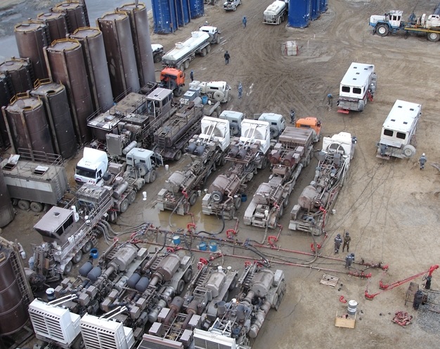
How can you simulate what will happen in the well when pumping fluid and proppant under high pressure? This is done by a specialized software called a hydraulic fracturing simulator, which uses a numerical physical and mathematical model of fracture development. The development of such software, like the development of any other software for the numerical simulation of physical processes, requires the simultaneous participation of physicists, mathematicians, high-performance parallel computing programmers and programmers who are able to create a convenient interface, because ultimately the hydraulic fracturing simulator will be used by engineers in the swamps of Western Siberia, mercilessly bitten by mosquitoes!
You can literally count the programs that allow you to calculate hydraulic fracturing, and all of them, until recently, were made only in one country in the world and were easily banned for sale in Russia. Yes, we are proud that we have developed and continue to develop the first industrial hydraulic fracturing simulator in our country - RN-GRID. Before our development, not only we, but the entire domestic industry was forced to use only American software, because, in fact, there was no other, and since 2014 there have been problems with the purchase of this software (as they say, there would be no happiness, but misfortune helped ). Now RN-GRID has not only completely replaced all similar software inside Rosneft, but is also being successfully sold to third-party companies.
To calculate a crack, a physical and mathematical model is needed. But which physical phenomena should be included in the model, and which ones can be "forgotten"? Surface pumps pump liquid under pressure with proppant mixed into it. This mixture enters the pipe, under pressure and its own weight descends to a depth, on the way experiencing friction against the pipe walls, braking due to its own viscosity and turbulence, loses some of its energy on perforations and, boring out these very perforations like an abrasive, enters the crack , moves along it, revealing it wider and wider, breaks through into weaker layers, gets stuck in narrow places and falls down under the action of gravity, and then is filtered through the walls of the crack in all directions, leaving the proppant in the crack.
The movement of the mixture and the opening (and then, after stopping the injection, and closing) the fracture is all a single task, which includes the mechanics of elastic deformation of the rock during fracture opening, and the hydrodynamics of the mixture movement through pipes and inside the fracture, and many particular problems like calculation of friction in pipes, disintegration of a jelly-like gel under the action of special chemistry, deceleration of proppant particles against each other, dissolution of the rock with acid (if it is not simple, but acid fracturing), heating the fluid by the rock and cooling the rock with the fluid, and many other effects. See for yourself how much is there!
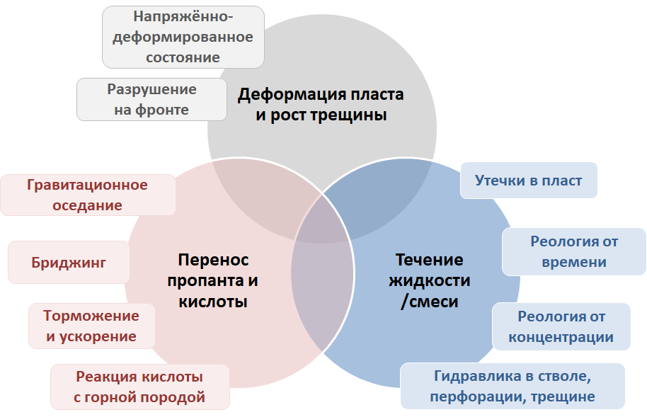
Thus, to describe all these processes, you need to sort through half of university textbooks on physics and a large part of textbooks on chemistry: continuum mechanics and hydrodynamics, thermodynamics and dynamics of chemical reactions. It is not enough to describe, it is also necessary to program, and then you have to overlap with textbooks on numerical methods and think how to discretize the problem and not get a system of equations that cannot be solved in a meaningful time. And then sit down to Intel's AVX2 processor instructions to make your nonlinear equation solver the best in the world.
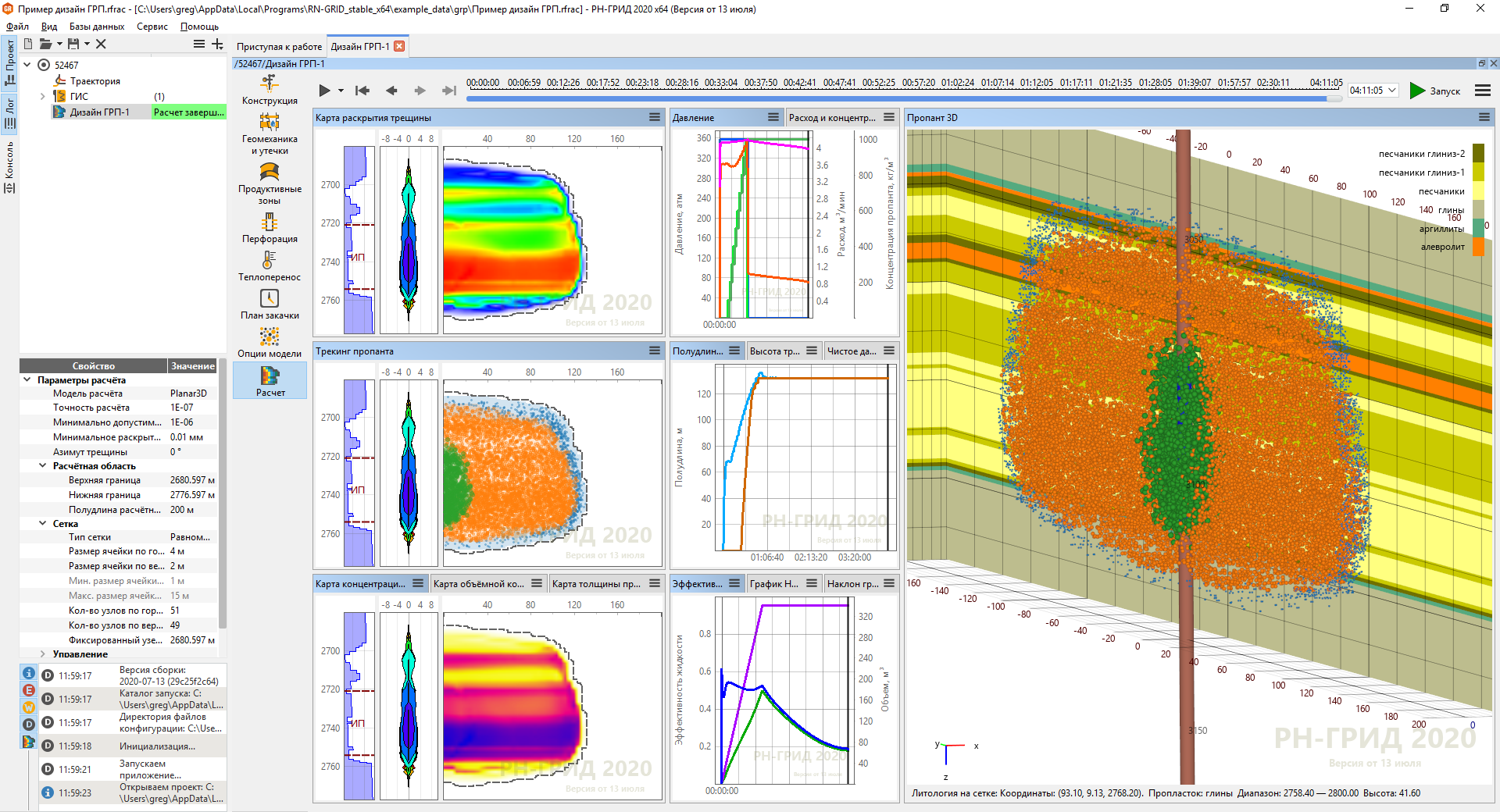
The result is the fastest and most sophisticated in the world ... console exe-shnik. To provide it with all the necessary data as input, and beautifully display the results of the calculation at the output, and then upload them to a report in the desired form, you will also need such a convenient application as a pre-post-processor. As a reminder, field engineers are rather tough guys who sit at night interpreting graphs and recalculating hydraulic fracturing designs. They are always ready to express everything they think about an eye-catching font or a button in a dialogue that goes off-screen on old laptop monitors 1024 by 768, which you, a programmer, lounging in your cozy office behind a pair of 4K monitors, forgot to foresee. And since the work goes on both day and night, they also love the dark theme very much:
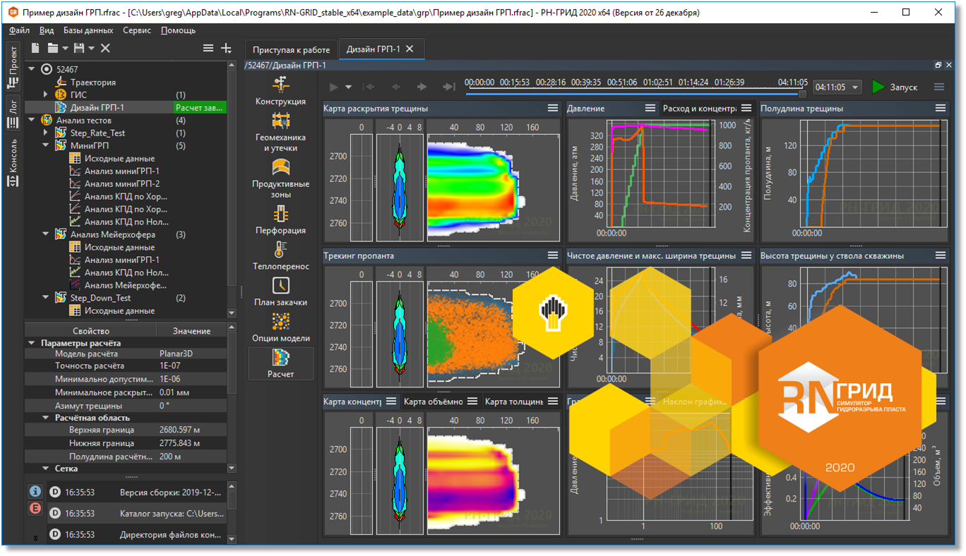
It should be borne in mind that everything described happens at a depth of several kilometers, and all that engineers see when performing hydraulic fracturing is the readings of several instruments on the surface and sometimes the readings of a pair of instruments lowered into the well. Therefore, it is important for engineers to plan in advance with the help of the model what will happen, then during the operation, according to the readings of the instruments, to see in time whether everything is going according to plan, to respond to emergency situations in time, and after the operation - to build a retrospective model of how the hydraulic fracturing was performed. so that the information obtained can be used in an adjacent well or in an adjacent field. We will talk more about the readings of the instruments below, because this module is needed for all technological operations.
Coiled tubing simulator
In surgery, from time immemorial, they have been accustomed to operations performed through a vein, and medical endoscopes have also been successfully used for a long time for research and manipulation of all kinds of human internal organs. The oil industry has its own analogue of this operation - it is a coiled tubing (CT) of a smaller diameter, which goes down into a conventional tubing and allows you to perform various kinds of work that would otherwise be difficult to perform.
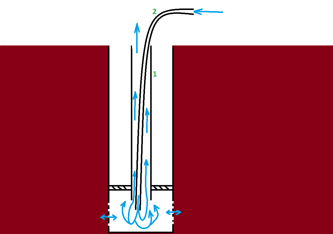
How is coiled tubing used? There are two main options. It might just be an open-ended flexible pipe. It is lowered into an ordinary pipe, through which injection or production was carried out before, and liquid and gas are pumped through it. But at the same time, they want them not to go into the reservoir, but to go up the pipe back. Look at the diagram, and you will understand the idea: pipe 2 is pushed into pipe 1, liquid and gas are supplied through pipe 2, and between pipe 1 and pipe 2 the injected liquid and gas rise back to the surface. Why is this needed? For example, if the main pipe 1 was half clogged with proppant as a result of a previous unsuccessful operation, it can be "flushed" in this way: the proppant will be carried back to the surface with a reverse flow of liquid and gas - this is called borehole flushing. For instance,if the connection of the well with the formation is clogged and does not allow oil to pass through well, more nitrogen can be injected with the liquid, then the formation pressure of the liquid will itself clean the bottomhole area. By controlling the pressure at the inlet to pipe 2 and at the outlet from pipe 1, we can ensure that the circulating fluid does not go into the formation, because we need to flush the well - or, on the contrary, it can leave if we pump acid to dilute the rock or unwanted pollution around the well.if we are pumping acid to dilute rock or unwanted contamination around the well.if we are pumping acid to dilute rock or unwanted contamination around the well.
The second option is even simpler - on the bottom of pipe 2 some kind of
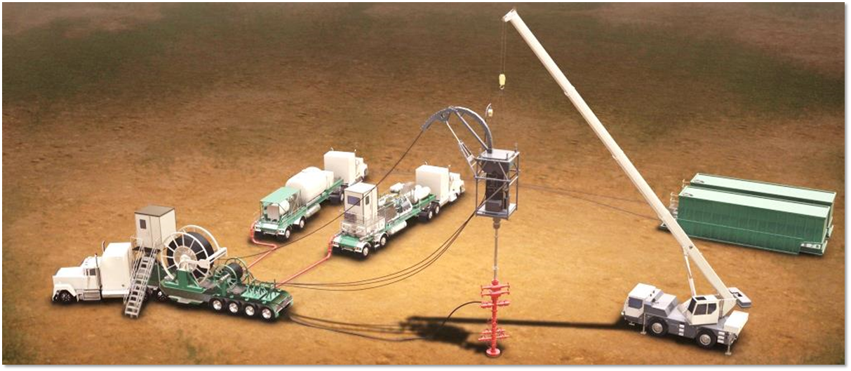
We at our institute are now developing our software for performing calculations of various operations performed through a flexible pipe - RN-VECTOR. Can you guess where the analogue, which is massively used in the vastness of the Russian Federation, was made, which engineers now have to use?
What needs to be modeled here? First, the loads on the flexible pipe. It will be lowered into another pipe, it will rub against the walls there, and first it will need to be pushed with additional effort, and then, on the contrary, held. But even when 2-3 kilometers of pipe are lowered into the well, all these 2-3 kilometers will be in very different conditions: the upper part will hang and stretch under its own weight, and the lower part, which has gone into the horizontal wellbore, will lie and try to get stuck ... Accordingly, it is important to calculate so that it does not "get stuck" or "break" anywhere. Calculation of various loads in accordance with the weight of the flexible pipe and its friction against the walls of the main pipe, the spiraling of the pipe and the mechanical properties of steel is the first part of any such product.
Secondly, hydraulics. At the entrance to the flexible pipe - one pressure, which is first lost when the fluid moves along the pipe wound on a bobbin, then is lost when moving down the flexible pipe, turns into some kind of pressure below. If suddenly there is more pressure below than in the reservoir, the liquid will go into the reservoir, lost, instead of going up between pipes 1 and 2 in the figure above. “Dear foreman of the brigade Ivan Ivanovich, - the worker of the CT brigade will say, - undoubtedly, we are seeing a loss of circulation, what do you think?” If, on the contrary, it turns out to be less, then oil will see through from the formation, and we are doing repairs at the well, and not doing production. So the simulator of this technological operation must be able to correctly calculate all pressure drops. By the way, the pressure in the flexible pipe inversely affects its loaded state.
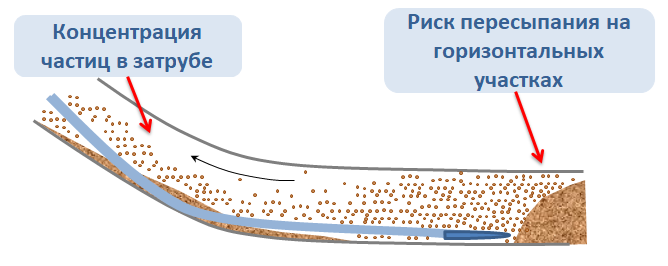
Third, the removal of particles. In the picture above, imagine agitated sand at the bottom of the well: will it rise upward with a stream of fluid, or will the flow rate not be sufficient and will it fall back down? And if you pump liquid together with nitrogen, the nitrogen bubble pushes the water upward faster, especially expanding on the way from the bottom up, but at the same time the sand itself cannot take out. How much "stirred up" sand can you take up without "dropping the pack"? We need a calculation, and with different flow regimes.
Fourthly, it is necessary to take into account the pipe fatigue. The flexible pipe is straightened from the drum, bent again on the gooseneck, then straightened again at the entrance to the well - and then everything is in the reverse order. The pipe is either lowered or raised, respectively, some of its parts are bent more, some less. The steel of the pipe is designed for a certain accumulated fatigue, and it is necessary to calculate the next addition of fatigue for each meter of the pipe from work to work and store this profile in the database. This is what this profile looks like after a certain amount of work:

Yes, of course, nobody canceled the flaw detector, and it will find and show possible violations in the pipe, but it is technically impossible or very expensive to check the pipe on it after each work.
Charts, charts, charts!
All the iron used during the coiled tubing operation and during the hydraulic fracturing operation is hung with sensors, somewhere more, somewhere less. During the operation, all data, of course, is written to a file or to a database, but in parallel, engineers need to set up a convenient appearance for all indicators so that they do not cut their eyes, and all indicators are in plain sight (pay attention to the weight units - how many newtons do you weigh?).
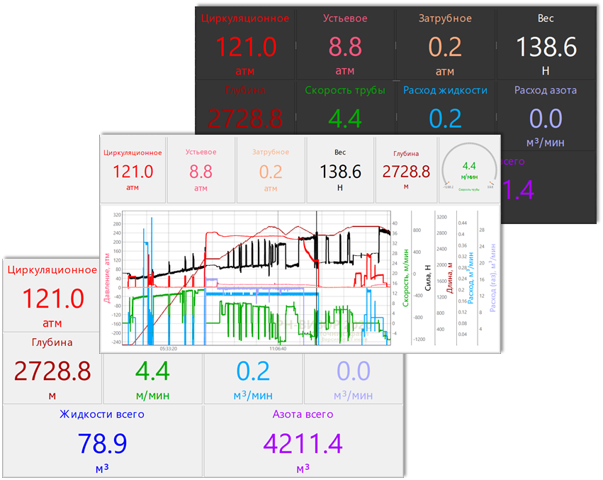
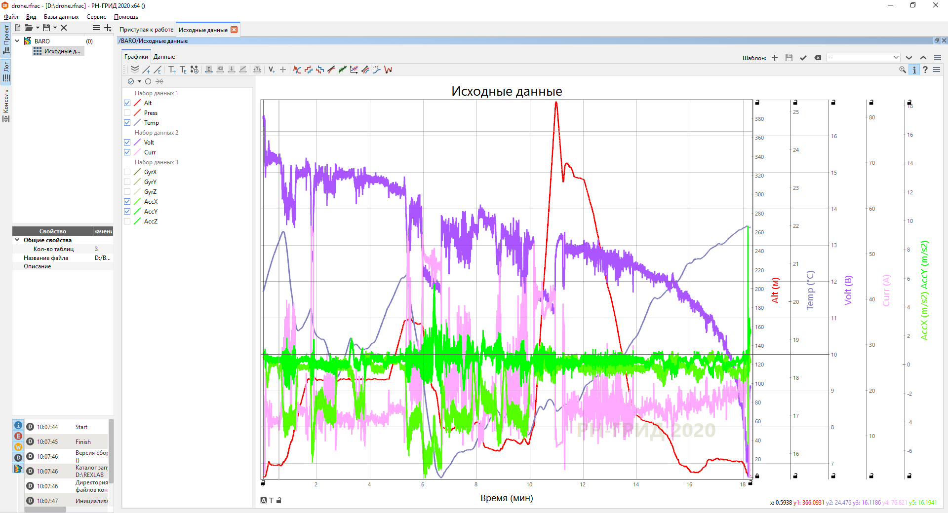
But after the end of the operation, the data file is imported, and all the graphs are displayed and thoughtfully analyzed, and it does not matter if it was working with coiled tubing or hydraulic fracturing. And when programmers and engineers are resting, they take their favorite software and load telemetry of their favorite quadcopter into it (because no other known software for some reason works so well with long data series):
But we deviated from the topic. For example, here is how a recorded fracturing operation might look like in the same software:
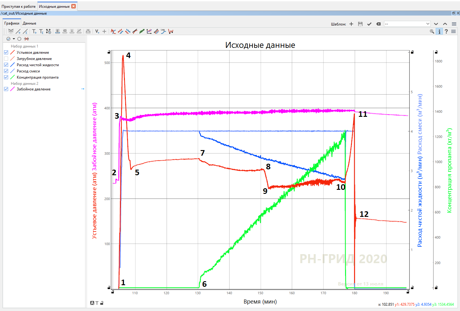
A competent engineer looks at these graphs, and the whole picture of what happened unfolds before him, like the lines of fate in the palm of his hand. At point 1, injection began, and the bottomhole pressure (pressure at the bottom of the well) begins to grow sharply from point 2 to point 3, until, finally, at a pressure of 380 atmospheres, a hydraulic fracture opens. Note that the pressure at the bottom of the well will remain almost constant until the fracture grows up to point 11. By the way, when the fracture opens at 380 atmospheres, the pressure gauge on the surface shows more than 500 atmospheres at point 4. The pressure in the fracture remains almost constant. and on the surface, the manometer readings fall from point 4 to point 5. The engineer will not even take an eye: he knows very well that it is almost water in the well that is replaced by the same gel,and the pressure loss due to friction in the pipe falls precisely by the difference between points 4 and 5. An inquisitive engineer will even measure the slope of the line from point 4 to point 5, and thus obtain the ratio of the friction coefficients of the fluid that was in the well and that is supplied there.
At point 6, proppant begins to flow, and see how immediately at point 7 the pressure gauge readings on the surface begin to fall - this is the liquid column in the well due to proppant becoming heavier and heavier. At point 8 to point 9, a friction reducer was added to the well so that the proppant would not slow down too much against the pipe walls. At point 10, they stopped supplying proppant, it ceased to "fall" into the well under its own weight, and therefore more pressure has to be pushed into the fracture, the wellhead pressure rises to point 11. And there the pumps are turned off, and the pressure instantly drops to point 12, and there already it begins to decline slowly as being of hydraulic fracture leaking
All these graphs provide a lot of information to an engineer who cannot clearly see what is happening there at depth, but thanks to knowledge, he can not only qualitatively assess what is happening, but also quantitatively evaluate many indicators. Let us deliberately leave out of brackets what is called "test injection analyzes", where all sorts of tricky rulers are applied to these graphs and with their help many unknown reservoir parameters are calculated. I think it's understandable how vast a field of activity for mathematicians, physicists, programmers and techies of all stripes is engineering software development!
The whole series:
- Part 1
- Part 2
- Part 3
- Part 4
- Part 5