Today's post will be devoted to the device for spot resistance welding of 18650 batteries and others. In the course, we will assemble such a device, analyze the basic principles of its operation, and examine in detail the welded places under a microscope. Batteries are not going to be easy today. It would seem a welding machine that literally consists of one transformer and a controller, what could go wrong here ?!
Imagine that one fine morning your screwdriver died. Tightening screws with a screwdriver is not a royal business, so you need to solve the problem. Nickel accumulators were the culprits, which prematurely went to Valhalla to drink wine and fight with swords. They were replaced by compact, high-current lithium-ion batteries, which are many times superior in performance to their predecessors.
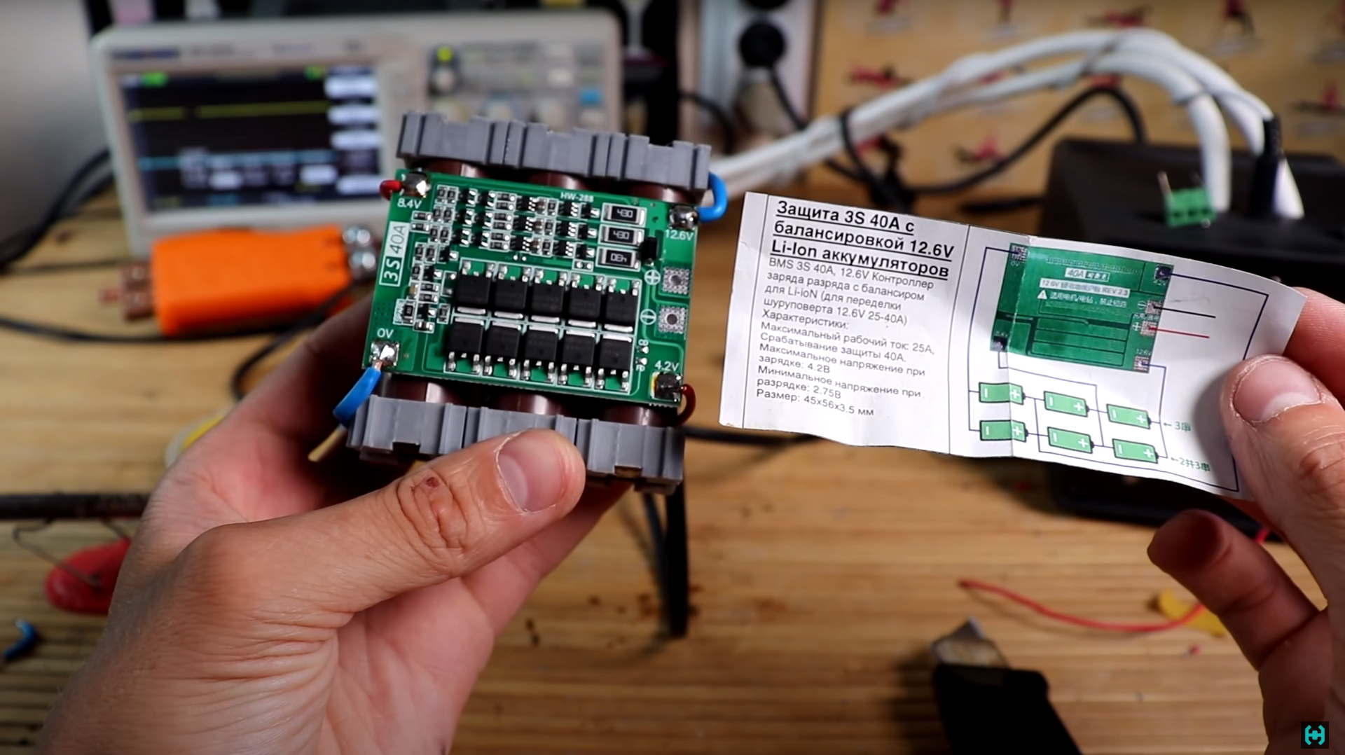
According to the technology, such cans are connected by spot contact welding, which welds the conductive tape to the battery body. It is not recommended to use a soldering iron here because of the possible overheating of the internals of the battery, which can lead to its premature failure. We install the so-called BMS board with a balancer on the assembly and assemble the screwdriver. Now he works like new. Vitya
pushed me to the idea of creating a welding machine .A person who literally repairs everything. For repacking batteries in various devices, he just uses an apparatus for spot resistance welding. The connection here turns out to be so strong that the tape literally comes off with the giblets. I was impressed by this device, and I had to figure out what and how it works.
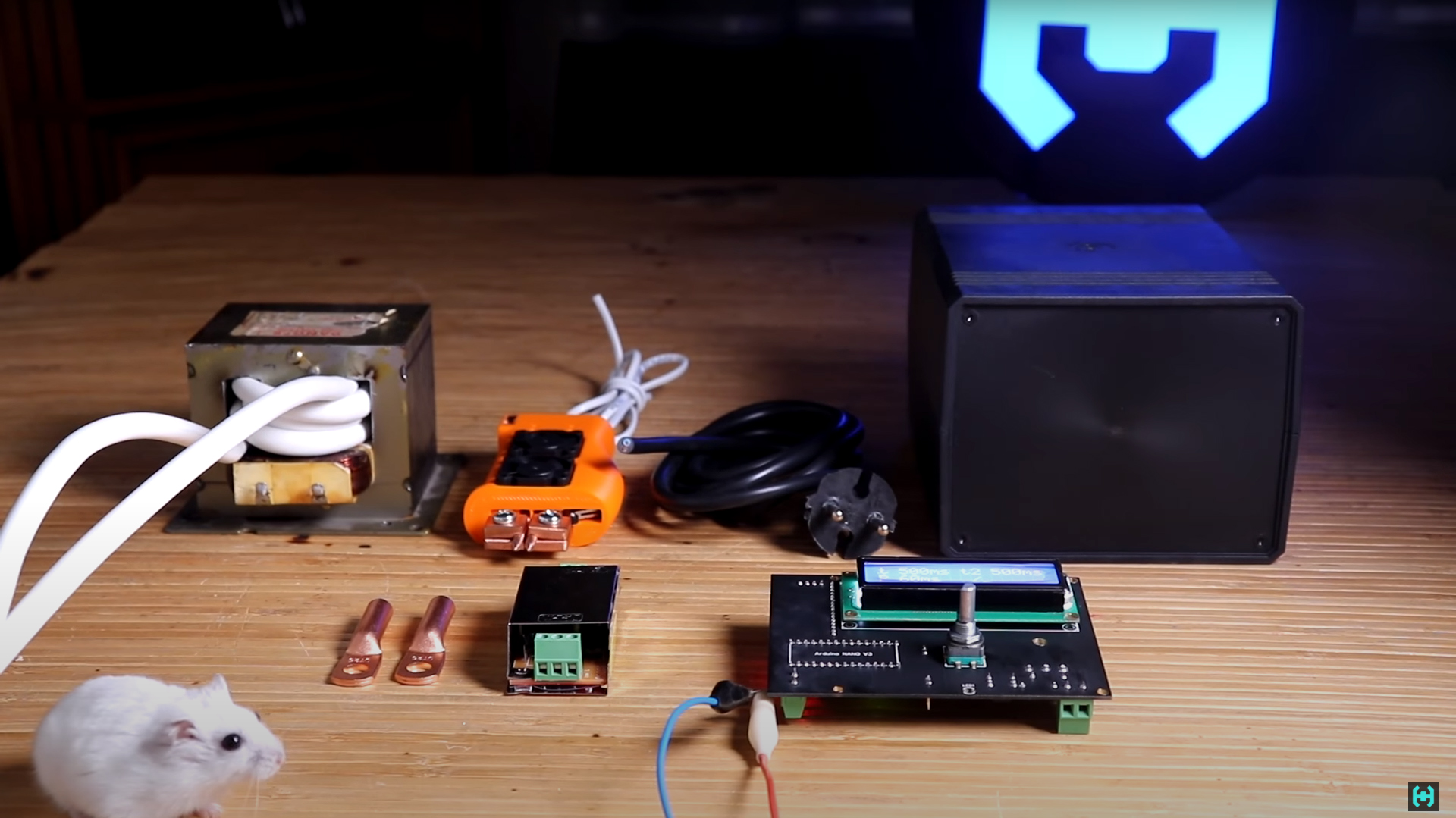
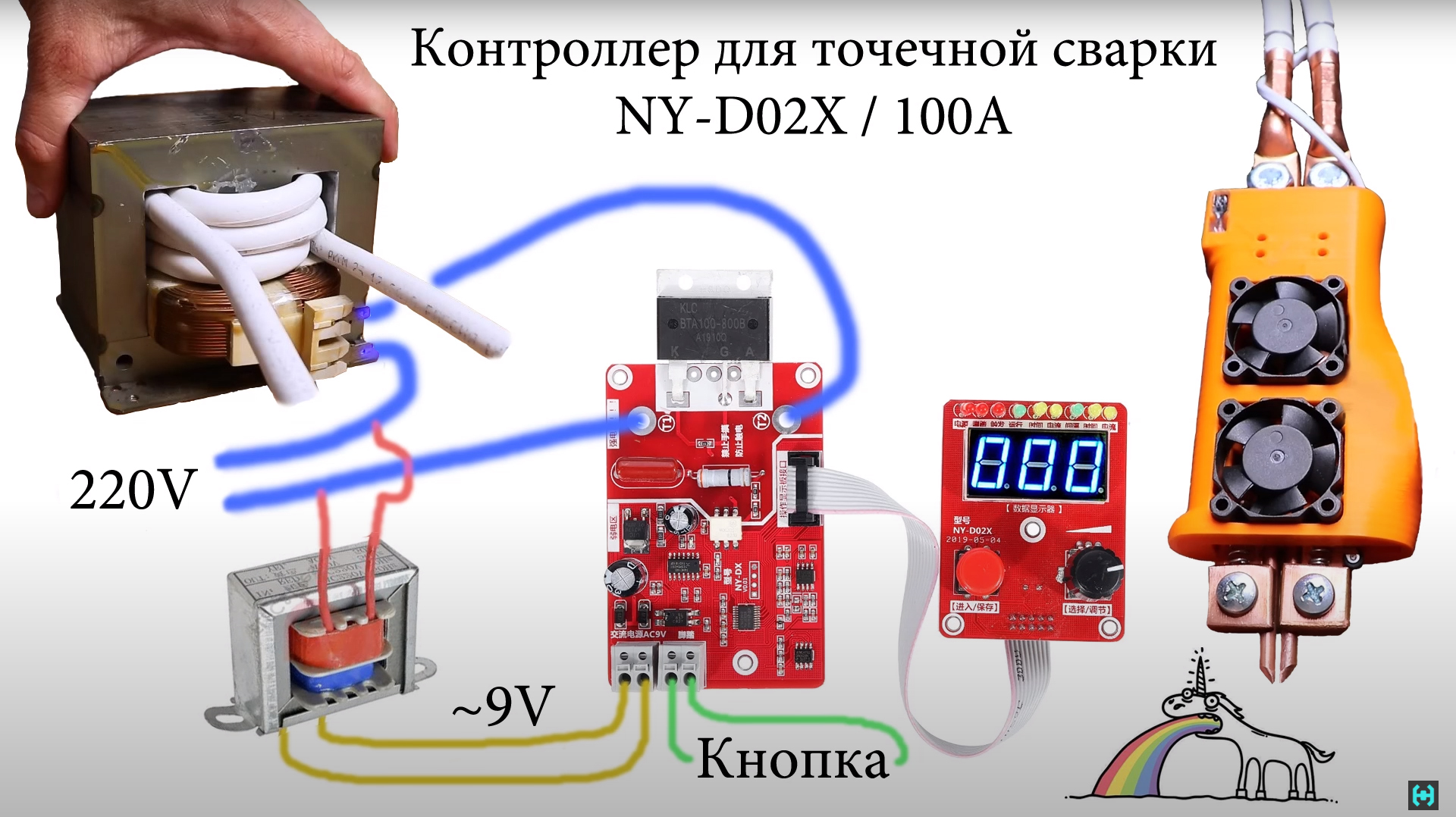
In fact, everything turned out to be quite simple here.The heart of the device is a microwave transformer with a rewound secondary winding, and a controller that connects the primary winding of the MOT to the mains supply voltage for the required time to generate a welding pulse. We also need a power supply for the controller, a pair of copper cable lugs, a 1.5 sq. mm. and a housing that will house all the electronics. I had a 700 W MOT with a cut-off secondary winding lying around for a long time, just there was a reason to attach it somewhere.
We remove the magnetic shunts and carefully clean the holes where the thick wire will be inserted. We pay special attention to the edges, they are quite sharp and can easily damage the cable insulation.
As for the cable itself, it's better not to save money here and take this comrade here.RCGM with a cross section of 25 sq. mm. Manufactured by Russia "Rybinskkabel". This is a tricky stranded wire, insulated from silicon-organic rubber of increased hardness, braided from fiberglass impregnated with enamel or heat-resistant varnish. It is very thin and flexible. Wire insulation is absolutely indifferent to high temperatures, the flame of a lighter is hardly capable of causing at least some smoldering. The length of the heat-resistant snake is 2.2 meters.
Lubricate the inner holes of the magnetic circuit with Vaseline.We carry out the same procedure with the cable. Despite the fact that the cable is quite thin compared to its cheaper counterparts, you should try to fit 4-5 turns into the transformer. But here's the bad luck. 700 W ILO allows to accommodate only 3 turns. No problem! A system of levers and screwdrivers comes to the rescue. In general, turning on ingenuity and winding 4 turns in such a small transformer.

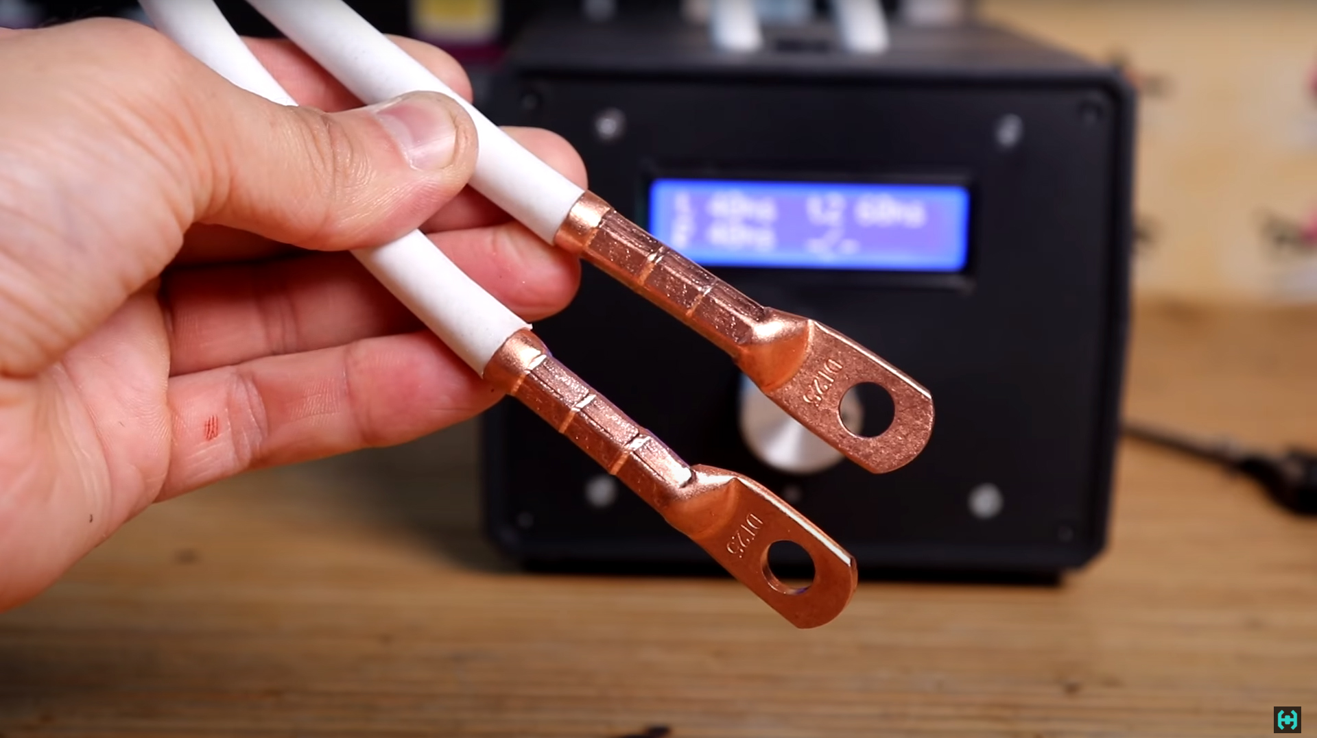
Cable lugs.Nice, copper, 25 squares. According to the technology, they need to be crimped with a special hydraulic press. Soldering is not considered here because of the possible heating of the wire in the course of further experiments. Crimping the wire here takes place in a 6-sided matrix, which evenly crimps the copper sleeve from all sides, creating a high-quality connection. After crimping, small ears may form on the tip, they must be removed with a file. As a result, we get beautiful crimped terminals at the ends of the wire.
Now they need to be connected to the copper bars on the resistance welding handle. The bolt here is 8 mm in diameter and 20 mm long. Be sure to install the Grover washer, it will provide a reliable hold if the connecting unit looses during operation.
The simplest handle for resistance welding can be ordered at aliexpress. But I liked the more advanced version created by one craftsman. His name is Gennady Zbuker . He himself assembles welding machines, supplements them with pens that he designs and prints on a 3D printer. This design is called the "ZBU 5.1" spot welding electrode holder with a button and springs. 3D models of early versions of such pens can be found on the Thingiverse website , the author made sure that, if desired, everyone could make a similar electrode holder with their own hands . It deserves respect! You can also order consumables on his website (not advertising, but a recommendation).
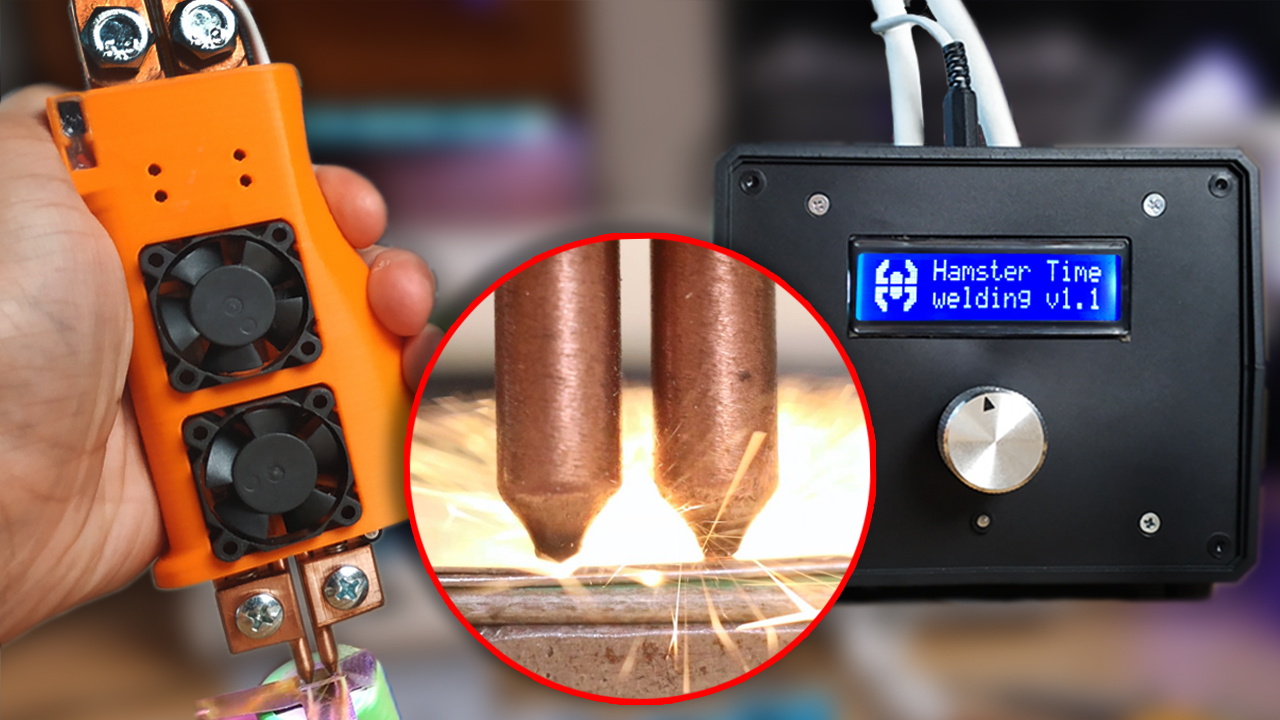
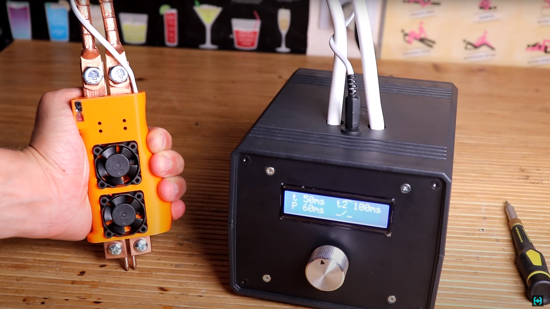
As for the handle for resistance welding.It is done quite well. The case is printed here with ABS plastic. The feature of version "5.1" is that there are two fans on board, which are capable of cooling copper busbars during continuous operation. They are powered from 5 volts via the micro USB connector. Consumption current no more than 300 mA.
From practice I will say that during all the experiments I did not succeed in heating the pen.The electrodes here are spring-loaded and have a "limit switch" button, which at a certain clamping force is triggered and gives a command for welding. This compression provides good electrical contact with the welded surfaces, guarantees repeatability of the weld spot quality, eliminates the formation of sparks and battery burn-through. Precisely because of the heating and simultaneous compression of the workpieces, this welding method was called "electric forging". If desired, the design of the electrodes on the handle can be changed for double-sided welding.

The electrodes are made of heat-resistant chrome bronze BrKhTsr.Since the electrodes wear out quickly during welding, requirements are imposed on them in terms of resistance to shape retention when heated to 600 degrees and shock compressive forces up to 5 kg per square millimeter. In the process of work, such electrodes do not particularly stick and do not burn. The current pulse for welding batteries must be very short, otherwise there is a chance to burn a hole in the case, which will lead to its failure.
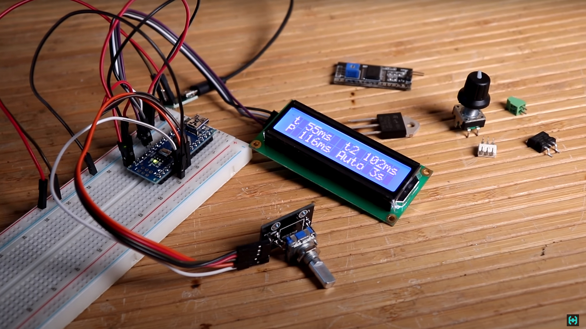
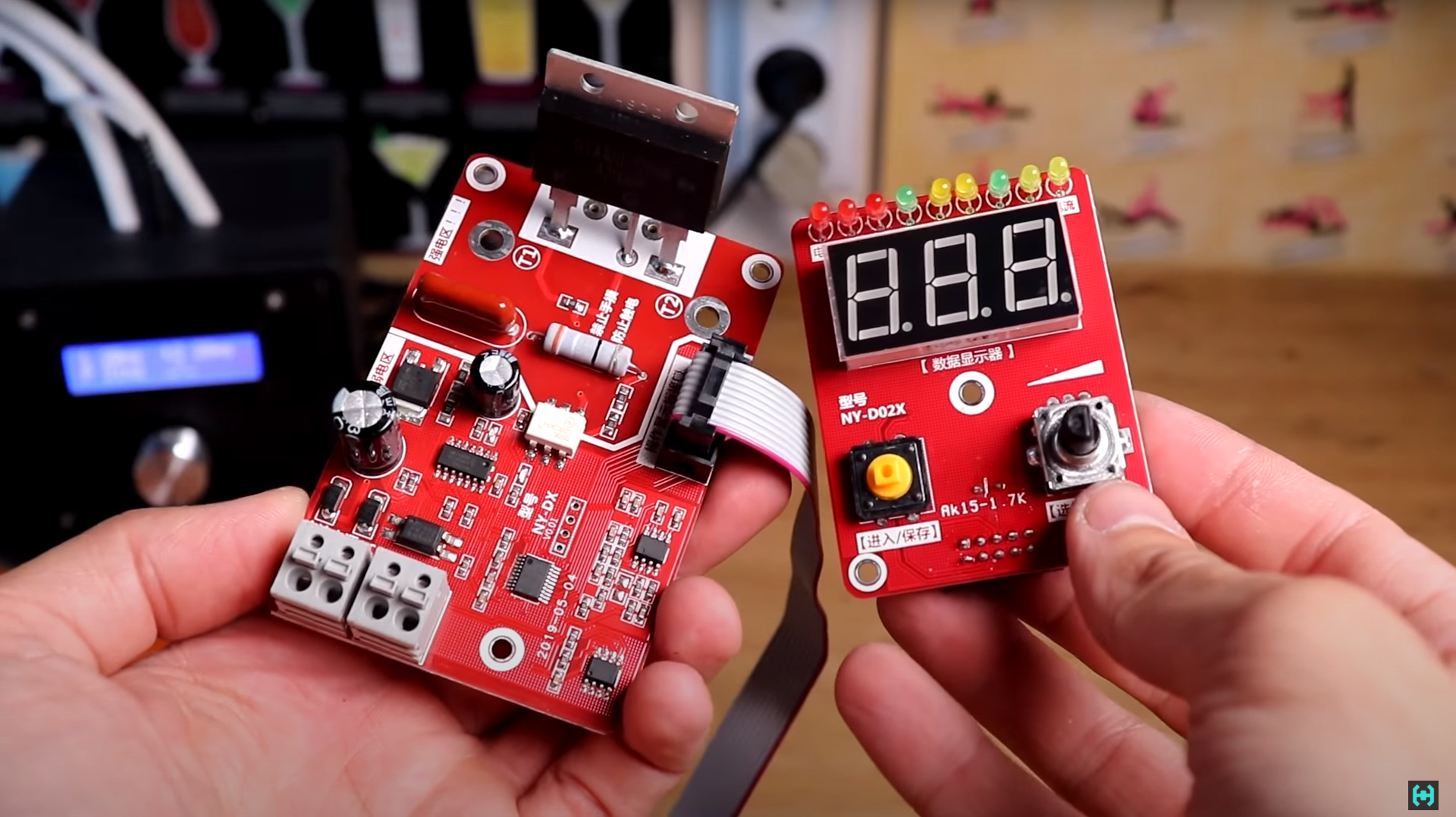
The task of controlling the pulse width lies with a fairly simple controller, which was taken from one site . The device is assembled on the basis of Arduino NANO, using a liquid crystal display to display useful information. Menu control is carried out using an encoder. Elementary and simple I thought, and began to assemble the device from the modules available on the farm.
The controller's functionality is pretty simple. It emits two consecutive impulses with a pause in between. The first impulse is called "additive", and the second "main". It welds metal to each other. All pulse time variables are adjustable by the encoder, including the pause between them. The power transformer is controlled by a fairly powerful 40 A triac. It is installed at the input of the primary winding. BTA41-600 marking.
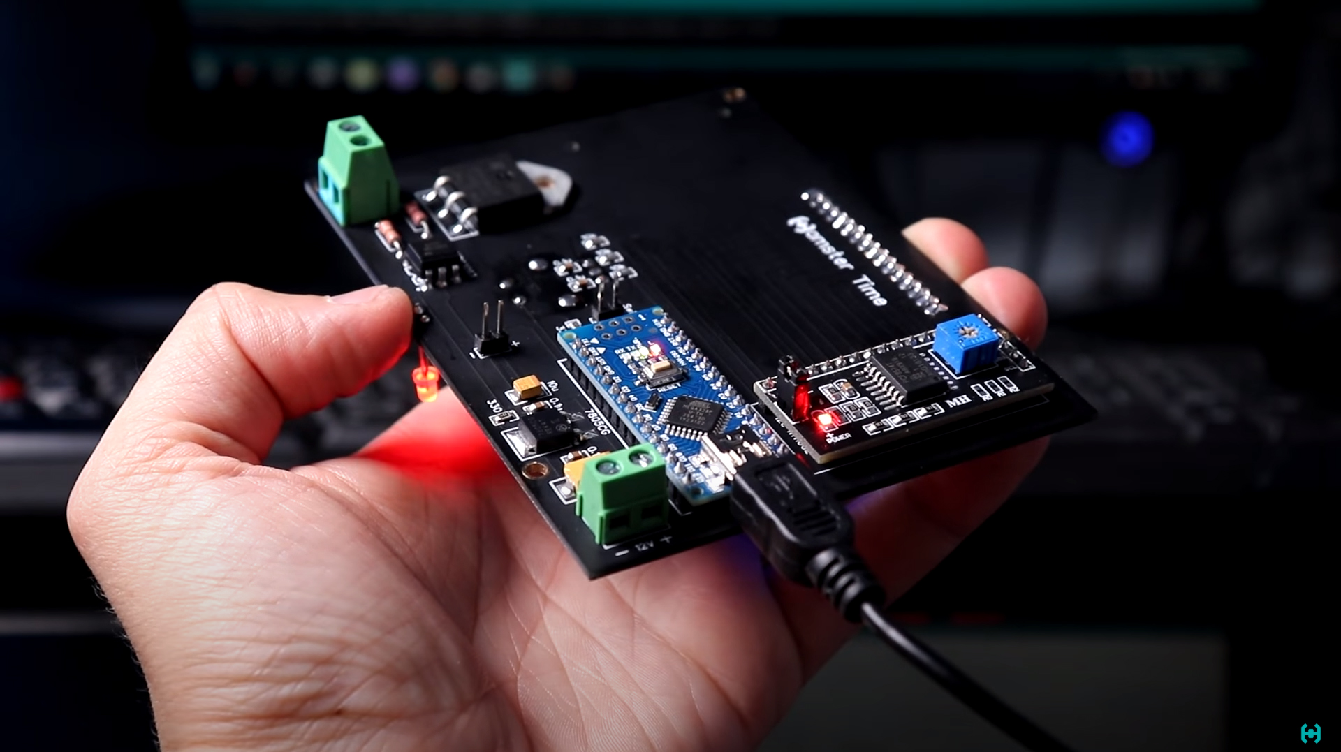
For the convenience of using the controller, all its modules can be placed on one board.This will allow you not to get confused in the heap of wires coming from the arduin. We poison the board and see how everything functions. The light is blinking, then the circuit is assembled correctly. The type of homemade boards today is gradually disappearing, because it is more profitable to order their production in China . The price really depends on the size in many respects, but that's another question.
We place the controller modules for resistance welding according to their specified locations.You've probably already noticed that the contacts on the board are gold-plated. It was interesting to see how they will show themselves during the soldering process. The peculiarity of gold-plated contacts is that they are not susceptible to various types of oxidation on the metal surface, which allows the boards to be stored for quite a long time. This is true for large industries. The solder also spreads over contacts such as butter in a frying pan.
After assembling the device, you need to upload a sketch to the arduina board. We do this through the FL Prog program in just a few clicks. The program is poured into the brain in a couple of seconds and all the necessary settings for further welding are displayed on the screen.
Now let's make a nice control panel.To do this, you need to mark all the necessary windows and future holes on the plastic panel. We carefully cut out the windows with a drill, and drill the holes with the screwdriver that we repaired at the beginning.
We place inside the ILO case, a 12 volt switching power supply and push the power cable inside. Its length is one and a half meters. We distribute all the necessary wires to our connectors, and in principle everything. With electronics sorted out.

As a result of all the manipulations, we got a pretty nice controller for spot welding.Power wires are led out through holes in the top cover of the case. There is also a connector for connecting the "limit switch" button. Everything is aesthetically pleasing and simple. It seems like it seemed to me. All channel subscribers know that nothing just happens. Something must go wrong. And this is one of those cases! It's time to test the device in action.
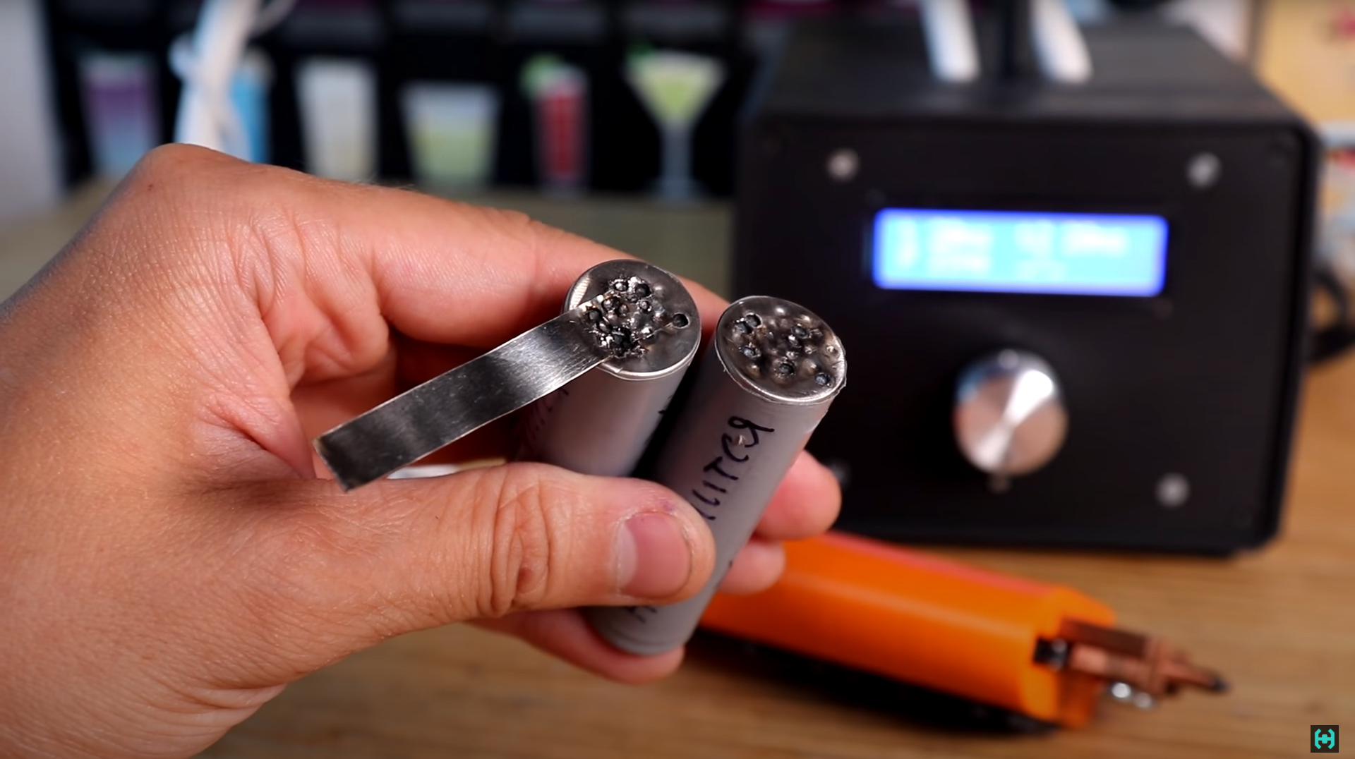
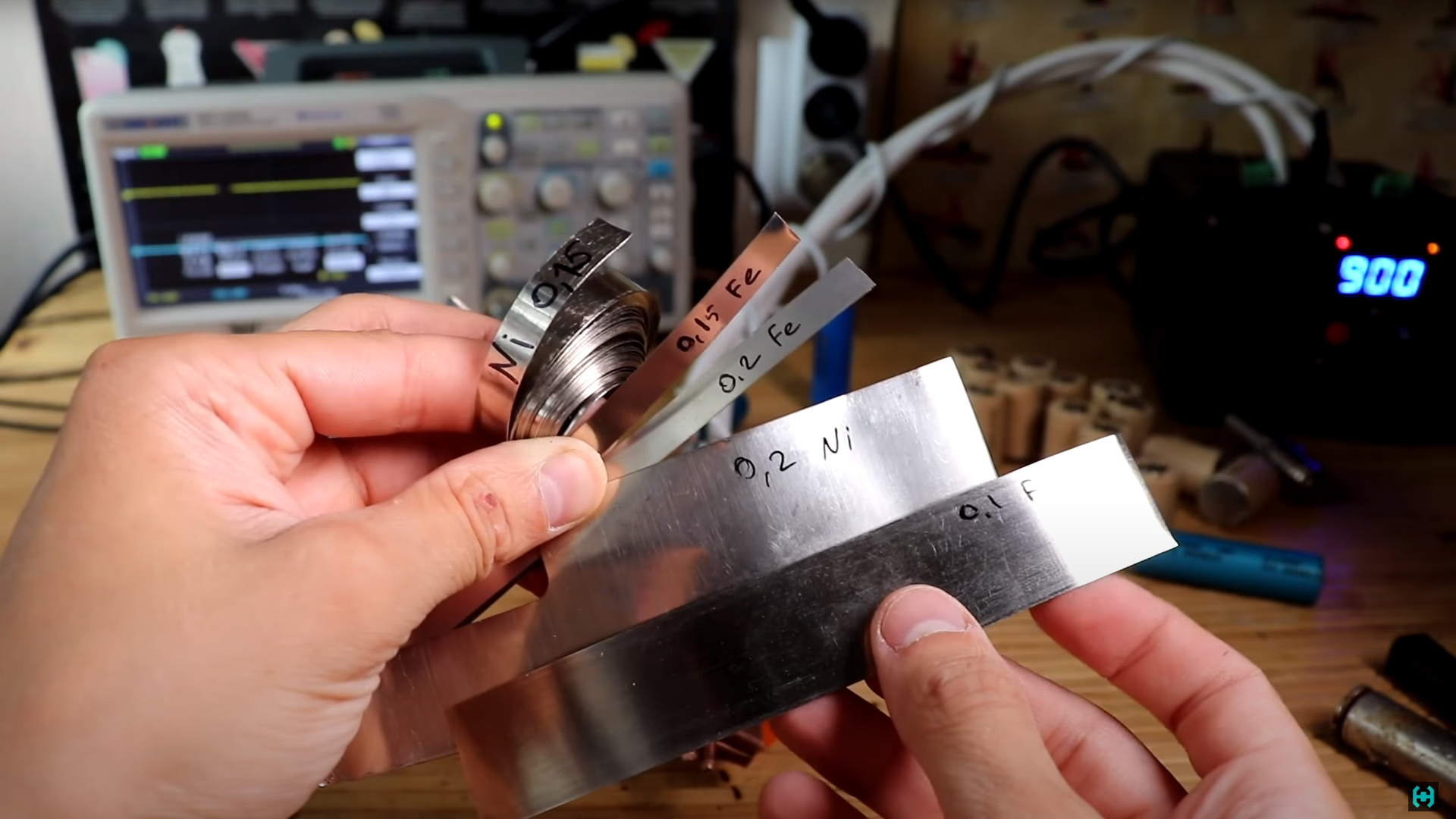
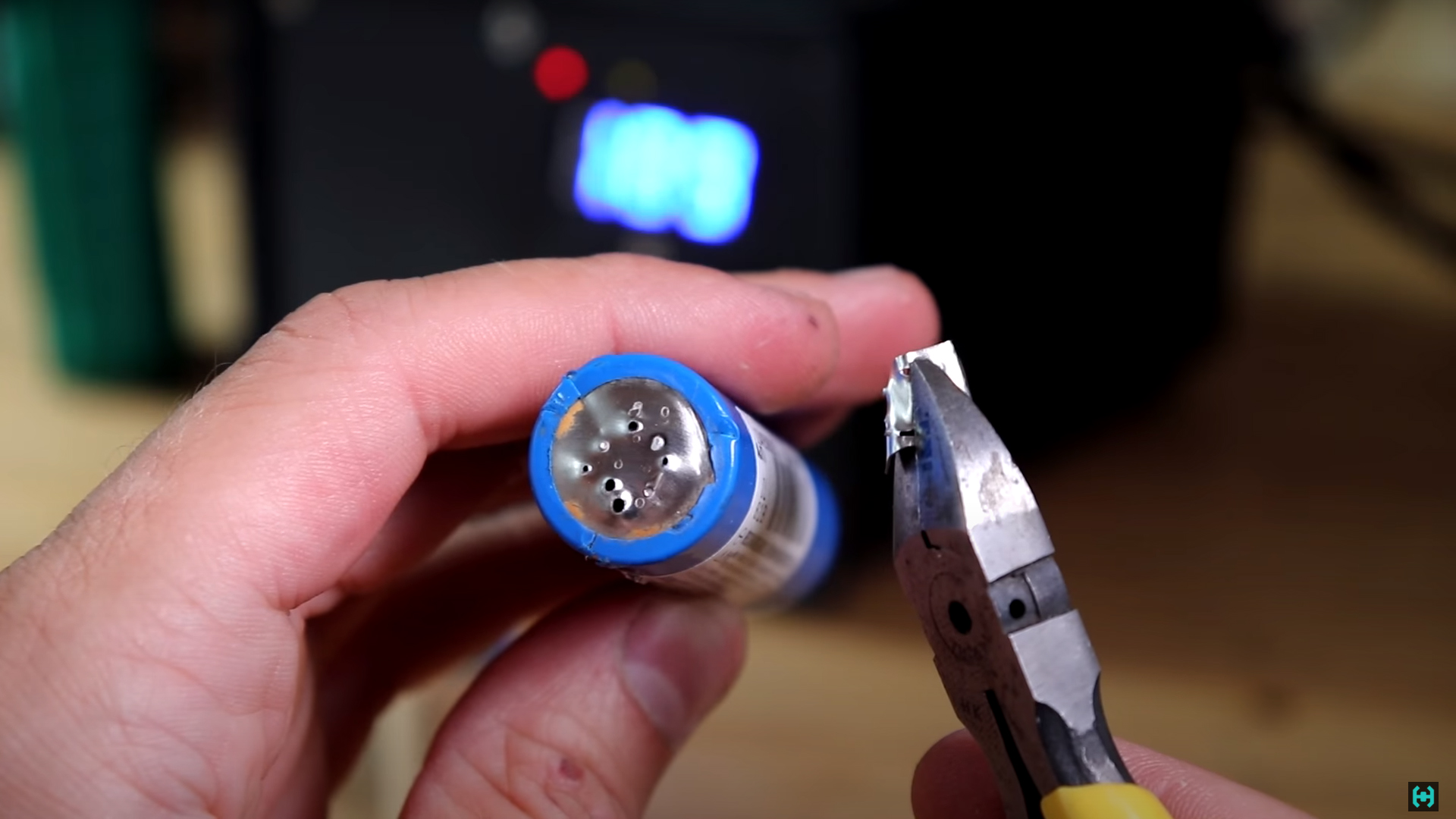
For welding, we take an old battery and a 0.15 mm thick nickel strip. Set the welding time to 20 ms for each pulse. This corresponds to one period of AC voltage from the network. If there is 50 Hz, then it is one fiftieth. As a result of the tests, it turned out that at the shortest time periods, the tape is not just cooked, but burned through. Now it's not a battery, but continuous ventilation ...
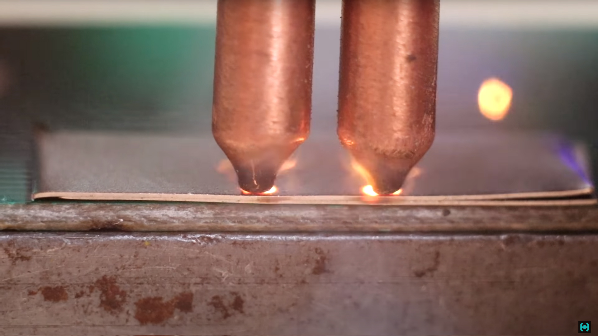
On other cans, welding took place a little differently, the piercing was less, but the tape between the electrodes was heated to red. It was pretty curious. Moreover, on some batteries, the tape was welded so that it practically could not be torn off, while on others, at the same welding time, there was no effect at all. The tape literally peeled off the case, leaving only two dents on the metal. A digital oscilloscope helped to understand the problem, which is able to record a signal for further study.
The reason for the burning out of the batteries was the operating time of the power transformer, which does not correspond to the established values.The problem here is clearly software, since the developer's sketch was repeatedly uploaded to another arduinka, but this did not give any result. Now, according to our set parameters, the signal on the optocoupler should be 10 and 60 ms. But in fact, this time is several times longer, 80 and 125 ms. Naturally, this time is enough to overheat the nickel plate between the electrodes and burn the bottom in some batteries.
If there are programmers among you, I have a request, look at the code and fix the error there. This is a good project in terms of simplicity and repetition, but it ended up with a pig in a poke. We tried to understand the jungle of this code, but the maximum knowledge we had was to render a picture when loading the program. In general, I am distant in these matters, but okay!
You need to get out of the situation.

There are ready-made spot welding controllers in China, order and wait. This is one of the most advanced board versions. Model NY-DO2X . In addition to the fact that it gives a double impulse with a pause, it is also possible to adjust the power. A triac is installed here BTA100 rated for a current of 100 amperes. The operating voltage is 1200 V.
We mark and cut out the holes for the new control panel.At this stage, we are not in a hurry so as not to cut off something crooked. We see several connectors on the board. The first one on the left is supplied with an alternating voltage of 9 volts. The second one connects a button from the electrode holder or an external pedal. The second option is good if you have a knob without a button, or just enjoy pedaling. The transformer for powering the board can be picked out from some old power supply from a home phone. A current of 300 mA is enough for your head.
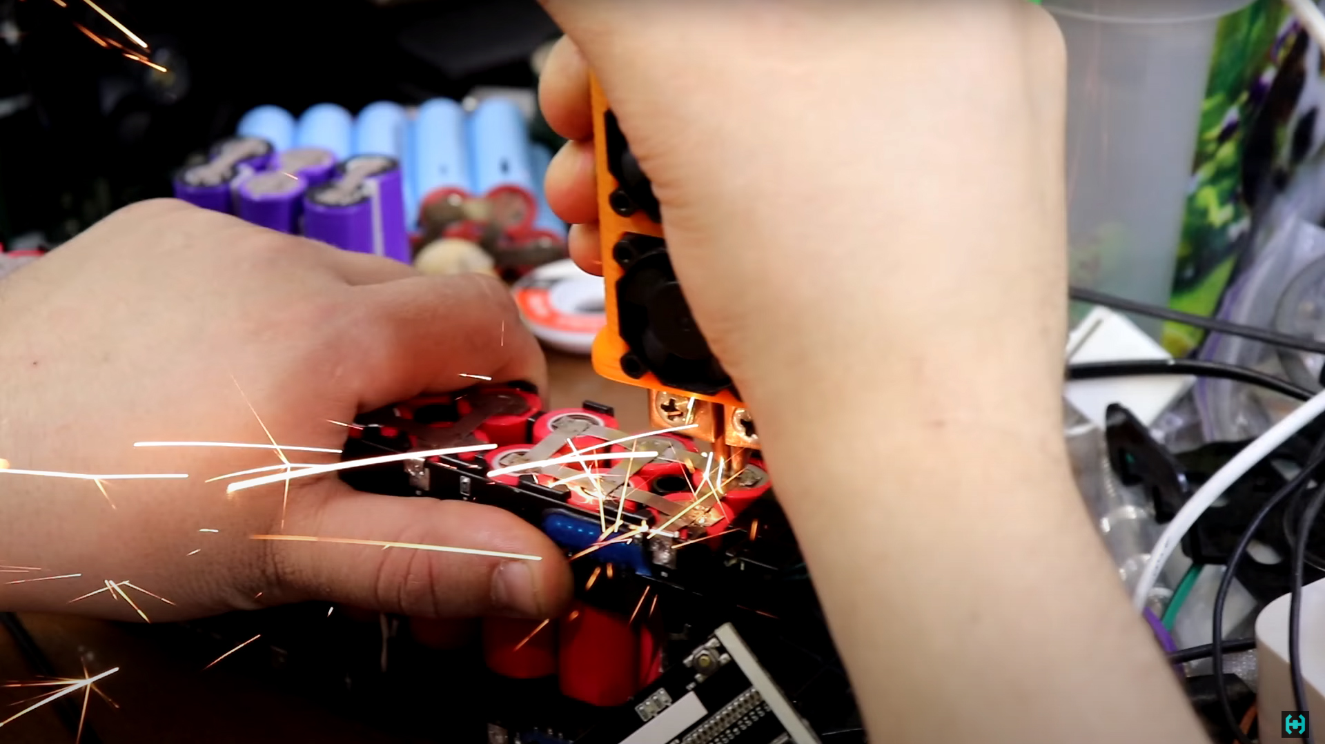
In general, we try to cook the tape to the battery.We press the handle, there is an impulse and what we have here. Cooking did not take place properly and the tape stuck to the electrodes. It feels like a 700 W transformer does not have enough power to weld a tape at short exposures. No question, I dress and go to the radio market for more powerful microwave ILOs.
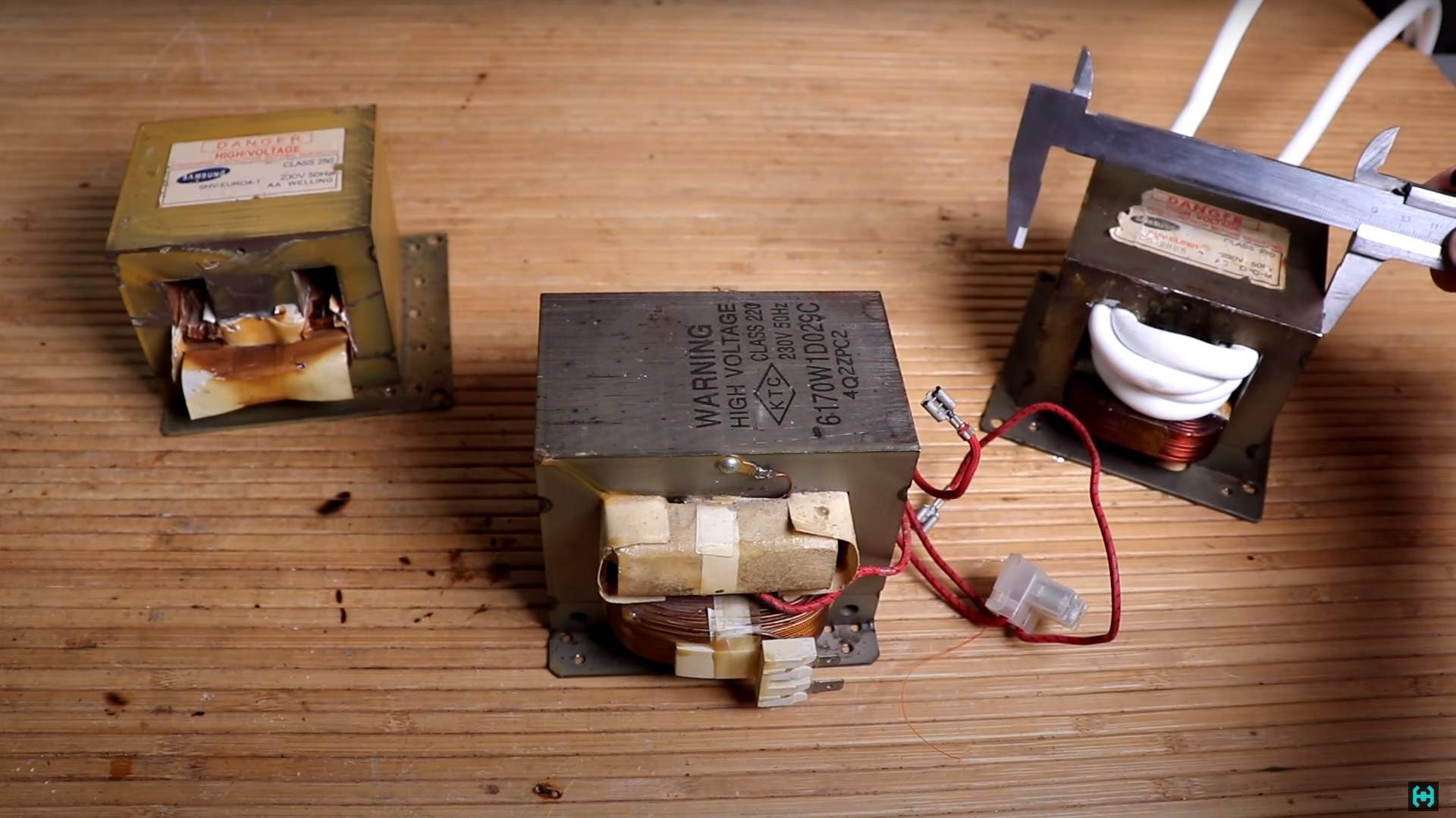
From left to right transformers: 700W, 800W and 900W. The larger the magnetic core, the more power. Here you can see how much the 900 W version is larger than its predecessor. Dimensions: length 106 mm, height 89 mm, width 66 mm.
More advanced welders can be made on sofMOTs from domestic microwaves, but firstly, they need a huge body, secondly, this is weight, and thirdly, not everyone can handle such a rare artifact. Let's not anger God, and let us put the transformer brought from the radio market under the knife. It is most convenient to cut the secondary winding with a hacksaw for metal. Copper is quite soft, so it cuts pretty quickly.
We knock out the wire from the core with an iron rod.In total, this operation takes 20 minutes. We don’t throw away copper braids, but rent them for scrap and buy beer. Be sure to remove the magnetic shunts that are installed for the soft operation of the magnetron and clean the edges of the holes in the magnetic circuit as shown earlier. Such a large transformer can easily fit 4 turns. If you wish, you can also accommodate the 5th, but I did not translate Vaseline) Consistently with a powerful triac, we solder the primary winding of the newly rewound ILO. We do not regret solder and do everything as for ourselves.
The connection diagram is just elementary.Even a child can handle it. It's time to try this "second" welding machine assembled in one film. In one of the next issues, there will be a triple fiasco poured on top with a thick layer of chocolate, where I flew another 600 bucks, taking someone else's infrared camera to use. In general, the channel is an expensive pleasure. Absorb other people's experience and other people's mistakes. Unlike me, you don't have to pay for them. Everything is free.
A quick guide to using a Chinese controller. Press and hold the red button for about 4 seconds. The device will enter the mains voltage calibration mode. It must be set according to the real readings of the multimeter inserted into the outlet. It is not clear why this function is needed, but the set numbers will change in proportion to the voltage in the network.
What do the bulbs above the numbers mean?The first LED indicates the presence of power. The second LED is on when the button on the handle is pressed. The third one lights up only when there is a pulse. In general, the first three red LEDs are purely informational. The fourth green light is the operating time counter, it sums up each press of the pedal or "limit switch" inside the welding heap. The counter is reset by double pressing the red button. Next is an orange LED. The first one sets the duration of the "first pulse". It is selected in periods. Let's set one that will be equal to 20 ms. The second LED sets the pulse power. Let's say 35 percent. Minimum 30 maximum 99.9%. The green LED between the orange ones defines the pause between pulses. Also in periods. Let's put 2. The last two orange LEDs also determine the duration and power, but already the "second pulse".Let's put 2 periods and turn the power by 100 percent. Actually that's all, now you can poke into some tape and see how the welding is going on, study the points, select the modes on the controller, and so on.

Brief characteristics of the resulting device for spot welding. The weight of the finished device came out to be 5.7 kg. The alternating voltage on the secondary winding of the MOT was 3.8 volts. The maximum current recorded during welding showed 450 amperes. This is associated with one interesting effect during the operation of the apparatus. The magnetic field at the wires comes out so large that they are scattered 20 centimeters apart from each other. The magnetic core attracts any nearby metal quite strongly, therefore I do not recommend using an iron case for the device, it will make unpleasant sounds when welding.
If the secondary winding is short-circuited, then even 700 W of the ILO is able to load the network up to values over 4 kW. How much more I do not know, since the wattmeter goes into defense when such a load is reached. At the same time, the secondary winding current goes off scale for 600 A, above the measurement limit of the multimeter. At the input of the primary winding, the maximum current is fixed at 21 amperes, while the voltage in the network sags from 230 to 217 volts.
With continuous operation, the core of the ILO will heat up, in 4 minutes its temperature will reach about 52 degrees. And this is idling with no load. In practice, as the temperature rises, the transformer begins to cook harder, this can lead to burnout of the battery. In this case, it is fair to blow the transformer with fans.

We turn exclusively to welding.First, let's see how the signal should look on the oscilloscope. Settings: the first impulse is one period of 30 percent, 2 periods are resting, the second impulse is two periods, the power to the entire coil. We make a weld spot and record the signal. We see what a cut-off period looks like with a power of 30 percent. After it comes the metal for two periods of rest, and then there is a powerful impulse with a duration of two periods and a power of one hundred percent.
The controller, by monitoring the phase transition through zero, opens the triac at 100 percent almost at zero voltage rise. It can be seen that the voltage and current go with a slight delay relative to each other. At 50 percent, the controller opens the triac only half-cycles of the mains voltage. This method is similar to Pulse Width Modulation. This mode is used in dimmers - dimmers. The glow brightness of an incandescent lamp will directly depend on the area of the cut sinusoid. In our case, this is necessary for all sorts of delicate welds.

Now our task is pretty simple.You need to weld the spot welding tape to the battery. But here a couple of questions arise. Which tape are we going to cook and to which battery? Remember the moment when our welder with a 700 W transformer refused to weld the nickel tape? The situation is identical with the new 900 W ILO.
At the beginning, for a long time I could not understand what the reason was, but there were two important points. The high-current battery, unlike the usual one, has a slightly thicker case wall. Perhaps the metal of the case is different. Our nickel tape is also pretty tricky. In the sum of all these factors, even powerful welding is not able to give the desired result.
The solution to the problem is to change the nickel strip to steel.It also seems to be nickel-plated on top, but in what follows we will simply call it steel. Welding on the same installations as before, welded the steel tape with a bang. To tear it off with nippers without destruction does not work. The assembled apparatus fully satisfied the assigned tasks.
Now let's look at the basic requirements for spot welding. The duration and power of the pulses must be selected in such a way that the welded places have as little overheating as possible. It appears in tarnishing colors around the weld points. This is not very good, since in these places the metal partially burns out, which can lead to a weakening of the strength characteristics of the joint. Ideal welding looks like this. There is no overheating, the dots are white, the tape comes off from the battery body with pieces. This is the result we must achieve.
Underwater rocks. There are a lot of them, first of all you need to understand the physics of current flow in a metal. The metal in the place of contact with the electrodes represents the greatest resistance to the current and therefore the place will be very hot. Our task is to heat up the metal to such an extent that a so-called welding core is created. Heating in this process should not occur under the electrodes themselves, but between the sheets of metal. In this case, welded cores must be made as quickly as possible, with a very powerful and short pulse. If you heat the welding place slowly, the heat will scatter through the battery in all directions, without achieving the desired result.

Electrodes are generally a separate world.Imagine you have been cooking an assembly of 18650 batteries for a long time and at one point you decided to sharpen them. The ends came out sharp, beautiful. But at the very first welded points, we will have a faded battery, since the electrodes are likely to sink into the body of the can. Some of these batteries are worth a fortune, and it is unacceptable to damage one of them.
What's really going on? The fact is, the sharper the electrode, the smaller its contact area with the metal, as a result, at the same current, the place will heat up faster. The welded core forms so quickly that it melts all the metal under the electrode.
Another very important point, when welding, the electrodes must be kept strictly perpendicular to the battery.They should not enter at an angle. A small bevel may form on the contact, which sooner or later will lead to burnout due to the uneven flow of current through the electrodes. In the same example, it becomes clear why the first additive pulse is needed at low power.
What does the distance between the electrodes affect? In theory, the further apart they are, the better. Less losses will be on the upper shunt blank. But as practice has shown, here you can play with the settings, and no matter what distance is, you can achieve good quality of welded points. It plays a big role with what width of the tape you are working with.
In general, setting the pulse duration and power is everything.I was able to weld 0.2 mm. a tape with such strength characteristics that it came off along with fragments of the battery case. All the batteries in the film were discharged if anything.
Recommendations when choosing welding settings. In this case, there are many factors affecting the final result. For example: you've found a mode that works well with the same tape and batteries. But, if you change one thing, the settings may also have to be changed. Now imagine that you have a bunch of motley batteries, how will you cook? The welding power and time must be adjusted from low to high. We put a point, the tape came off, it's okay, we raise the power and watch. Now the tape comes off with giblets. Exactly what is needed. Well, do you understand everything?
I think it is worthwhile to list again all the factors that can affect the final result of spot welding.
Electrical wiring in the apartment. An extension cord with a cross section of 2.5 squares was made especially for the film. Even in spite of this, the weak 700 W MOT managed to squander the network under load.
The main welding characteristics depend on the power of the transformer, on the cross-section of the power wire, its length, the number of turns, the quality of the connecting nodes with the manual contact.
An important role is played by the material of the electrodes, the distance between them, sharpening and clamping force. A lot is determined by the material of the tape for resistance welding, its thickness, width and shape. Battery type and wall thickness. Even the temperature of the ILO is worth considering.
Based on all of the above, in each individual case, the settings for the first and second pulses on the controller are selected to obtain the best welded cores with the lowest tarnish colors.
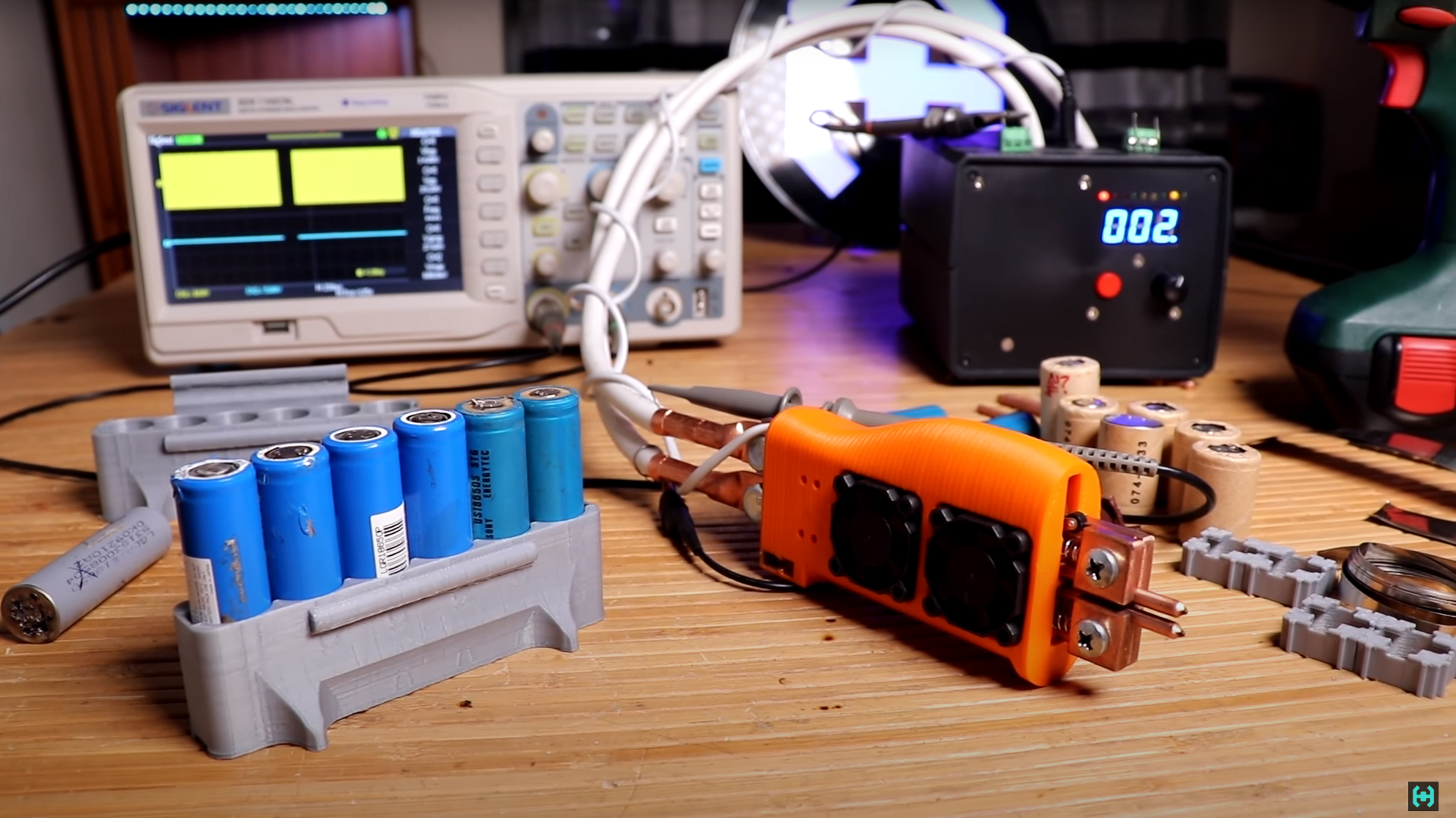
The assembled device for resistance welding turned out to be quite compact and versatile. He was only going to weld batteries for a screwdriver and a soldering iron from China, which needs a 24 volt power supply. Often a portable tool is missing during repairs. Cell constructorfor 18650 batteries we printed on a 3D printer, they simplify the task of forming assemblies with different voltages and capacities, allowing you to add elements in any sequence. The assemblies are interconnected with special grooves. Now repacking your old scooter by yourself will not be difficult.
For reference. The filming of this episode took a little over 2 months. When I started studying this topic, I could not even think that there would be so many nuances. In terms of cost, the film's budget exceeded the expected boundaries, since almost 2 welding machines had to buy spare parts. In total, 3 meters of nickel strip was used up and 2 good batteries were damaged. Two dozen bad ones were used up.
Well, everything, the video was voiced, now you can go to drink and prepare for the next release.
As Master Yoda said: To
listen to you - everything is so difficult. Do you hear what I said?
- You must feel the power, it is between you, me and the stone, everywhere ...
- Yes ... nooo
Full video of the project on YouTube
Archive with useful things
Our Instagram