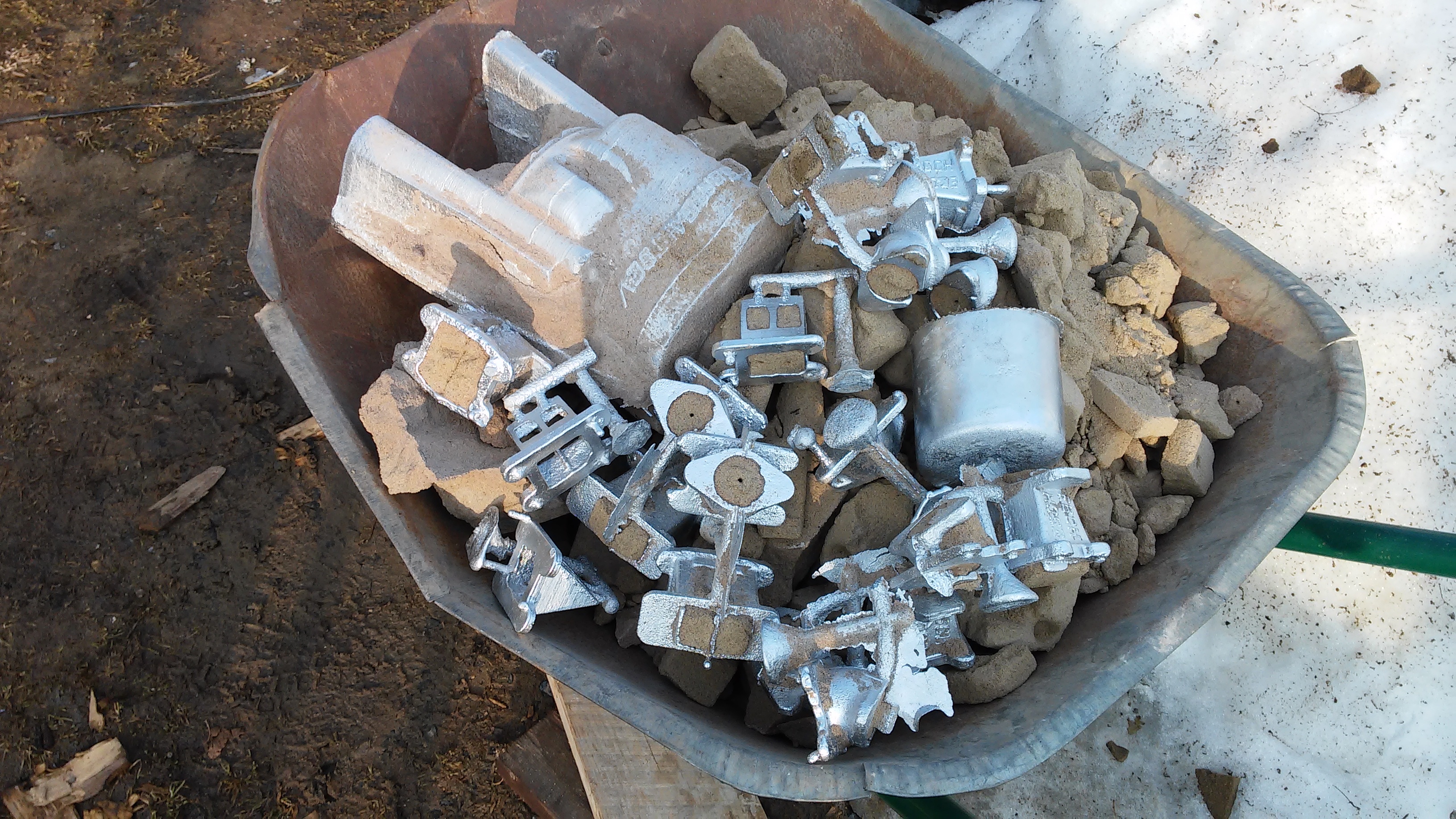
6 years have passed since the release of the first and last note on this project ( Own 2-stroke engine. CR620recommended for review). Then I stopped due to problems with outsourcing in metalworking. Some cannot, some do not want, some do it indefinitely, some do not want to return the details. And the city in which I live has a glorious industrial history and was the center of the Petrovsk industry of the 18th century, but now there is one root in the name of the city and several operating enterprises that employ about a few percent of the population from the glorious past. And now it’s not the 90s and not even the 00s, when it was possible to agree with a person from the factory so that he would do something like that for you. Now they have a job and a checkpoint at the entrance, as I later learned - nominal. This whole story with the transfer of details where they lie, and not made, the search for new places and the like wandering lasted for several years. It turned outthat I was able to cast a complex aluminum casting near the shed in the parental dacha, but to process what did not look like a problem initially - no.
At the same time, I met a master from the university workshop, who, first under supervision, and then on his own, allowed me to work on machines. The only pity is that the machines were slightly larger than the bench-top and my casting did not have a chance to get into them. However, I made small parts on them for sale and earned money on an industrial-grade lathe, albeit one produced at a factory of dubious reputation in the ARSSR.

From the premises where I could do something, there was a 3x3m piece of a barn in my parents' dacha and a garage-shell. In one there is no place in another light. I decided that the problem with electricity was easier and moved the machine to the garage. There I washed it, sorted it out and studied it. It would seem that there is electricity in the cooperative opposite through the bushes and a primer, 10m away. I contacted the chairman and asked him to pay all fees for the right to buy electricity from his cooperative. He was categorically against it. Feil. I also failed to convince the pensioners' neighbors. Feil. There was an idea to rent a garage with friends for storing and repairing motor vehicles. They called on the ads, went to look, and each time the communication with the owner of the premises ended after the question of installing the machine. Feil. The project has been postponed for next year as usual.
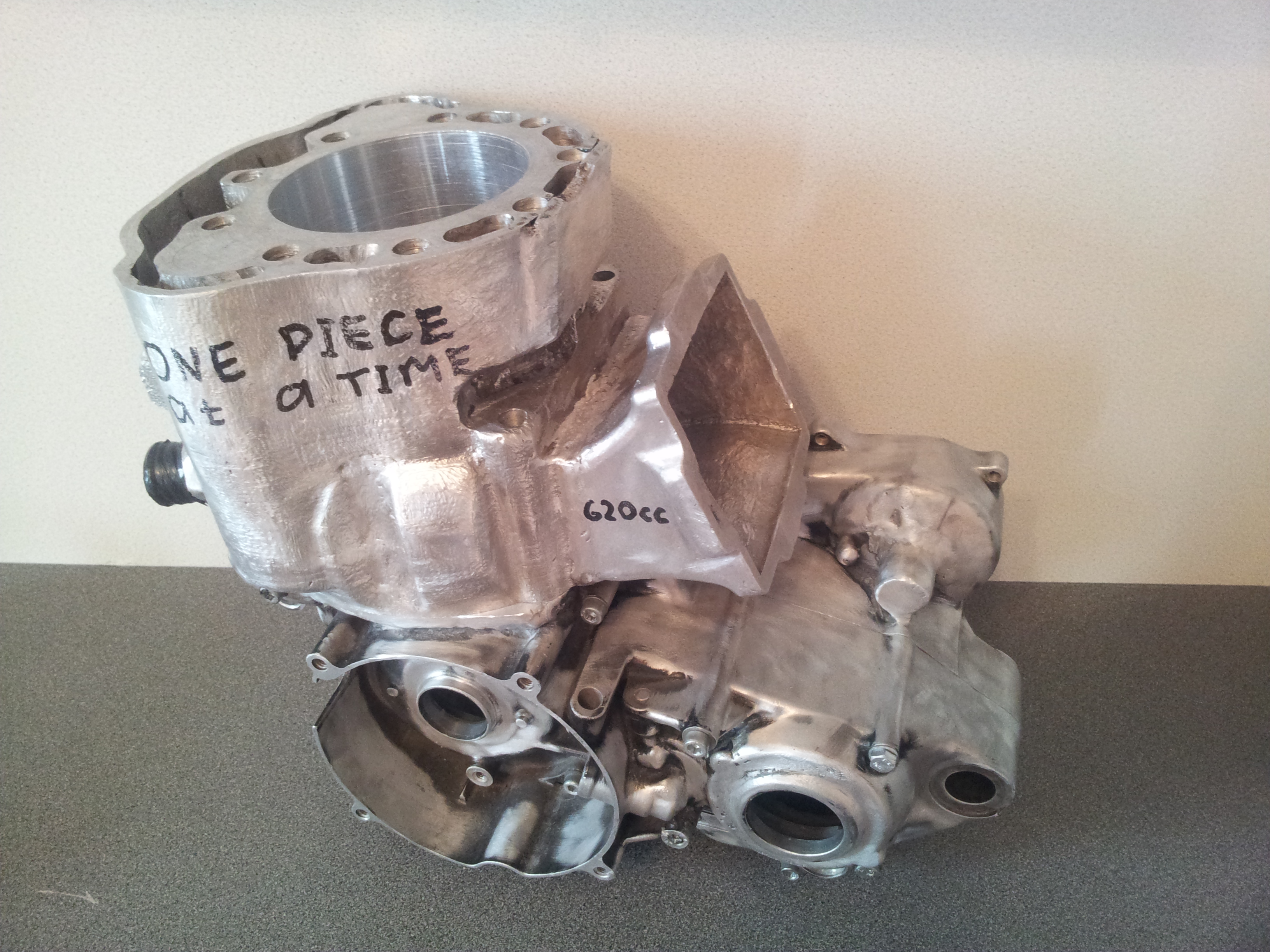
By the end of the summer of the following year, I, apparently, tired my parents so much with waste heaps of foundry in the country (in my opinion, they diluted the rural landscape well and got rid of mowing the grass within a couple of meters from them) that they decided to buy me a garage near the house and with electricity , already with three phases along the wall. There, finally, the lathe came to life, and I was able to start processing the cylinder casting after 2.5 years of exposure.
When I finally processed the casting, I ran into another problem: I made an agreement with a person who makes superhard galvanic coatings on the cylinders of an internal combustion engine and designed the cylinder specifically for the coating, and while time passed, the person had already stopped doing this or simply did not take it, while others either they did it expensively, or they were somehow very suspiciously confused in the answers. In addition, the spool wells were made vertical; when designing, I could not think like a technologist, because I did not have my own production base. These I could not handle myself and gave it to the side, where the cylinder hung for six months. So the project got up, I wanted to finish it by the summer, it never happened and now again. It was necessary to make a cast-iron sleeve, but only by that time so many new ideas had accumulated that the 4-year-old project was outdated and there was no desire to drag it.So this branch stopped forever.
A new version of the cylinder was prepared in winter. It is from this moment that the chronology of the project can be counted. Its distinctive feature is the abundance of "mechanization" - two valves in the exhaust channels and spools in the purge channels.
Let's start with a little theory about power valves in two-stroke internal combustion engines.
Introduction
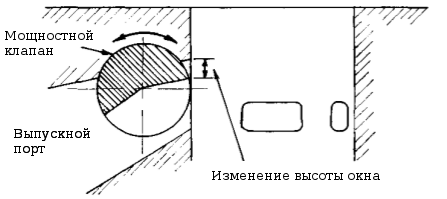
To date, two-stroke engines with crank-chamber blowing are used to control the section and / or phase of the exhaust port. These systems provide a smooth power curve. Changing the phase or cross-section of the outlet port is performed using a flap located in the outlet channel. Its position depends on the speed of the crankshaft. The damper drive can be pneumatic, mechanical or electrical. For example, on a Yamaha TZ500 motorcycle at high rpm, about 10,500 min-1, the exhaust phase is 202deg, and at low rpm about 180deg. The illustration shows the Yamaha power valve design.
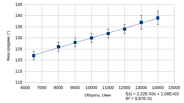
As for the outlet, for the purge there is also a dependence of the optimal purge phase on the rpm, due to the compromise between the gas velocity in the purge stream, the loss of fresh mixture through the outlet, and the volume of fresh mixture supplied during the purge. This dependence is linear, as can be seen from the graph below.
In contrast to the outlet port, the purge channels are also characterized by the exit angles: horizontal and vertical. In the case of five-channel blowing, usually four non-zero and different horizontal angles and five (two for 1-4 channels and one for 5th) vertical angles are obtained.
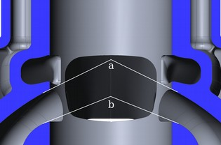
Horizontal angles of the purge ports: A, B, C, D

Vertical angles of the main purge channels
These angles are required to obtain a characteristic purge loop. This method of blowing is called loop blowing and provides the most efficient removal of exhaust gases without increasing the number of moving parts of the engine and complicating its design. Therefore, at present, only it is used on all two-stroke engines, except for two-stroke diesel engines. Due to the importance of the outlet angles of the purge passages, the methods used to control the outlet cannot be applied. As they will either create unwanted turbulence in the purge channel or change its exit angles.
Authors [A. Graham Bell. Two-Stroke Performance Tuning. Haynes Publishing, 1999.] claim that natural frequency oscillations occur during purging. :
Where:
- the speed of sound in the purge channel;
- the volume of the crank chamber without taking into account the volume of the purge channels;
- the average length of the purge channel;
- the average cross-sectional area of the blowing channel;
is the width of the average cross-section of the channel;
- the height of the average cross-section of the channel.
Expression is an amendment that takes into account the influence of the inlet of the purge channel.
This natural frequency, , must be equal to:
Where:
is the cleanliness of the engine crankshaft revolutions;
- purge phase.
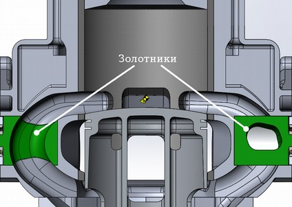
Thus, from expression (2) it follows that the natural frequency of oscillations arising during purging is directly proportional to the engine speed, but the right-hand side of expression (1) does not depend on the crankshaft speed. Therefore, the purge works optimally only in a narrow range of revolutions, and to expand the operating range, it is necessary to add the dependence on the revolutions to the right side of expression (1). The easiest way to do this is by introducing the dependence of the average cross-sectional area of the purge channel on the revolutions. In order not to introduce undesirable eddies into the gas flow in the purge channel, it is desirable to change the cross section of the purge channels by changing their number. For example, using spools that block some of the purge channels. Within the framework of this project, it is proposed to block the additional purge channels with spools.
: ,
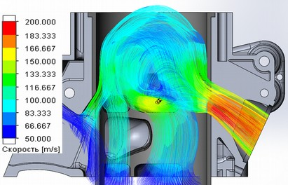
The influence of this solution was investigated using computer simulation of blowdown in the SolidWorks Flow Simulation software package. The purging is performed at a constant pressure difference between the inlet to the purge channels and the outlet from the outlet channel. The piston was considered stationary and at the bottom dead center. The intake and exhaust processes were not considered. The pressure difference was selected from the difference in volumes under the piston at the bottom and top dead center and was 0.6 kg / cm2. Due to the above assumptions, the calculation results in this stationary approximation can be considered as qualitative without quantitative assessment. Since, for example, it is impossible to separate the exhaust and purge processes in time or space. This is the main difficulty for computer modeling of two-stroke engines with crank-chamber blowing.
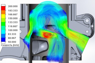
The figures show that the closing of the spools significantly affects the distribution of flow rates and the type of the purge loop: with closed additional channels (three-channel mode), the gas velocity increases during the purging process and the purge loop becomes more pronounced and distant from the outlet window, which should reduce the loss of fresh mixture through the outlet port and reduce the residual gas ratio, at the same time, a high flow rate at the outlet of the purge channels during three-channel purging indicates the presence of a bottleneck that will limit the gas flow through the engine, and hence the power at high rpm. In the case of a five-channel mode, the mixing of gases must be greater, which means that the coefficient of residual gases will increase, but at the same time a lower speed is observed, and the exhaust channel becomes a "bottleneck"which reduces the loss of fresh mixture through it.
2000 ( )
2000 ( )
In addition to spools in the purge channels, it is planned to install a power valve (MC) in the exhaust channel to check the joint operation of both systems. The valve in the form of a sector spool is best suited for the MK actuator. This is due to the fact that the edge of the flap of such a power valve in the entire range of the working stroke is as close as possible to the working surface of the cylinder (that is, at a small angle of rotation, the trajectory of the movement to the point on the edge of the valve is close to a straight line), and not only in the lower position, as in in the case of a cylindrical spool or an inclined gate. In addition, such a damper design does not create strong vortexes behind itself, as a gate damper moving parallel to the cylinder axis.
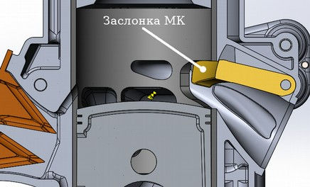
Power valve flap (MK) in the lowered state
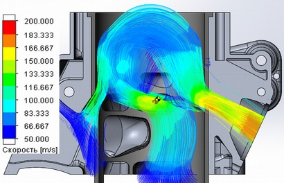
Purge with closed spools in additional purge channels and lowered MK damper
Model development
Based on the information (table) obtained during the study of the cylinders of the Kawasaki KX500, Honda CR500, Yamaha YZ490 and CZ 514 motorcycles, the purge and exhaust phases were chosen equal to 125deg and 186deg, respectively, with a fully closed power valve, the exhaust phase is reduced to 156 °. The number of purging channels was chosen to be five and the outlet from two main windows and two additional ports. A petal valve was installed at the inlet.
| Piston stroke, mm | Connecting rod length, mm | Outlet height, mm | Purge window height, mm | Release phase, deg. | Purge phase, deg. | |
|---|---|---|---|---|---|---|
| Honda cr500 | 79 | 144 | 34 | 15.5 | 180.1 | 119.5 |
| Yamaha YZ490 | 82 | 137 | 37.8 | 16.8 | 188.5 | 123.7 |
| Cezet type 514 | 72 | 130 | 32 | 17 | 183.4 | 131.5 |
| Kawasaki kx500 | 86 | 145 | 36.5 / 40 | 17 | 180.1 / 189.3 | 121.3 |
| CR724 project | 79 | 144 | 26/36 | 17 | 156 / 185.8 | 125.3 |
Note: If the cell contains two parameters of the height of the outlet window or the release phase, then the first refers to the state with fully closed MC, and the second with open.
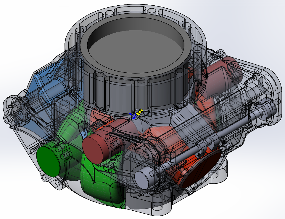
After measurements of the elements of the base engine mated to the cylinder, a three-dimensional solid model of the gas distribution channels and cavities associated with them was created. All drawings were made using the SolidWorks software package.
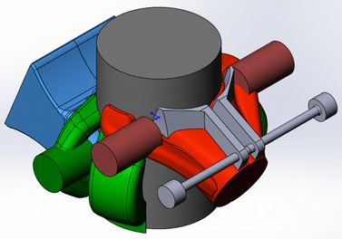
Solid model of gas distribution channels
Starting with a solid model of channels allows you to minimize the number of thick casting spots and reduce its weight. In the next step, a shell with a wall thickness of 4-6 mm and a bottom mounting flange was built around the channel model.
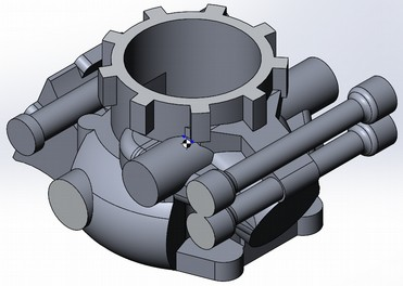
Channel shell without channel model cutout
The cooling jacket was obtained by constructing a second shell around the channel shell, such that a distance of 6-10 mm remained between both shells in hot spots (the upper part of the cylinder and the discharge channels). The wall thickness of the shell of the cooling channels is about 4 mm. The inlet to the cooling jacket is located at the bottom of the cylinder under the outlet channel and above the upper edge of the purge channels, the jacket covers the entire perimeter of the cylinder. Also, at this stage, the planes of the gas distribution covers and the intake and exhaust flanges were built.
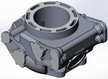
Solid model of a cylinder without a cut of the channel
model The cylinder model is obtained by subtracting from the channel model obtained at the previous stage, thus the channel model forms cavities. Further, the marking of the mounting holes, bearing landings and liners was made. This completes the construction of the cylinder model.
The construction of the liner and spools was carried out in the same way by subtracting the model of the channels from the corresponding solid "blanks".
It turned out and so much text, so for the sim I finish this part. The next one will tell about the manufacture of foundry equipment and the execution of cylinder casting.
Next part: Your own 2-stroke engine: sandbox, Easter cakes and 10kg of molten metal