Introduction
Good day, friends! Recently at work we got a brand new iCE40 UltraPlus Mobile Development Platform board from Lattice Semiconductor. According to the developers on the iCE40 UltraPlus official website, the MDP is a board that contains 4 iCE40 UltraPlus FPGAs, each of which controls its own set of peripherals. The set includes:
- mobile display with a resolution of 240x240 with MIPI DSI interface;
- image sensor with a resolution of 640x480 (OVM7692);
- low-power microphones in the amount of 4 pieces;
- BLE module for wireless data transmission;
- programmable SPI Flash memory;
- pack of various sensors (pressure, compass, gyroscope and accelerometer);
- well, all sorts of buttons and bulbs.
The whole cool thing about this whale is that with the help of special software packages, you can deploy neural networks to work with video and sound. And this is not to mention the fact that Lattice FPGAs are low-power, small-sized and fairly cheap.
UltraPlus MDP

As a test case, blink the RGB LED (D13 in the diagram, highlighted in red in the picture on the left). After reviewing the documentation, we conclude that the LED is controlled by the FPGA number U3 (highlighted in red in the picture on the right). We also learn from the documentation that the LED is controlled by a built-in PWM modulator and a current driver.
We take note of this information.
Setting up the board and writing a program
There is a group of jumpers on the board, with which you can select the FPGA that needs to be flashed to work with the selected group of peripheral devices. We are interested in three groups of jumpers responsible for pulling up the power supply to the LED and programming the desired FPGA.

The procedure is as follows:
- Set switch SW5 to ON / OFF position
- Two jumpers on J19 horizontally
- J26 , 1-2 3-4 ( . , )
- J17, J25, J27 9-10 ( )
Yes, I understand, it's all boring, but without it it won't work.
Also, in order to connect the clock signal generator, it is necessary to set the jumper jumper J23 to position 2-3 (the numbering goes from the top).

Now the program. To create a bit file for the iCE40 UltraPlus MDP firmware, you need the Lattice iCE cube 2 development environment ( link to the product page ) and to flash the Programmer and Deployment Tool board itself . The product is licensed, but after registration, the license can be obtained here www.latticesemi.com/Support/Licensing/DiamondAndiCEcube2SoftwareLicensing/iceCube2
The editor in the IDE is very inconvenient, so I wrote in Sublime Text, but to each his own.
Here is a general scheme that gave an understanding of what and where to do:

So the PWM modulator and current driver, which I mentioned earlier, have surfaced. These two devices are internal modules. It is necessary to write a logic control device and send data for this whole kitchen to work properly. Let's start in order, describing the "black box":
entity DriverRGB is
	port (
		-- RGB Led:
		LED0 	: out std_logic;
		LED1 	: out std_logic;
		LED2 	: out std_logic );
end DriverRGB;
Sync initialization is missing in the black box. For this, an internal module is used, which is declared as follows:
-- Generator clock:
component SB_HFOSC is
	generic (
		CLKHF_DIV	: string := "0b00" );
	port (
		CLKHFPU	: in std_logic;
		CLKHFEN	: in std_logic;

		CLKHF 	: out std_logic );
end component;
 This module can generate a signal with frequencies of 48MHz, 24MHz, 12MHz and 6MHz. The parameter CLKHF_DIV is responsible for the frequency division factor ("0b00", "0b01", "0b10", "0b11", respectively). CLKHFPU and CLKHFEN enable the module to work. CLKHF - clock signal.
Next, we declare the PWM modulator and the current driver:
-- Embedded PWM IP:
component SB_LEDDA_IP is
	port (
		LEDDCS		: in std_logic;
		LEDDCLK		: in std_logic;
		LEDDDAT7	: in std_logic;
		LEDDDAT6	: in std_logic;
		LEDDDAT5	: in std_logic;
		LEDDDAT4	: in std_logic;
		LEDDDAT3	: in std_logic;
		LEDDDAT2	: in std_logic;
		LEDDDAT1	: in std_logic;
		LEDDDAT0	: in std_logic;
		LEDDADDR3	: in std_logic;
		LEDDADDR2	: in std_logic;
		LEDDADDR1	: in std_logic;
		LEDDADDR0	: in std_logic;
		LEDDDEN 	: in std_logic;
		LEDDEXE		: in std_logic;
		LEDDRST		: in std_logic;

		PWMOUT0		: out std_logic;
		PWMOUT1		: out std_logic;
		PWMOUT2		: out std_logic;
		LEDDON		: out std_logic );
end component;
-- RGB Driver:
component SB_RGBA_DRV is
	generic (
		CURRENT_MODE	: string := "0b0";
		RGB0_CURRENT	: string := "0b000000";
		RGB1_CURRENT	: string := "0b000000";
		RGB2_CURRENT	: string := "0b000000" );
	port (
		CURREN		: in std_logic;
		RGBLEDEN	: in std_logic;
		RGB0PWM		: in std_logic;
		RGB1PWM		: in std_logic;
		RGB2PWM		: in std_logic;

		RGB0 		: out std_logic;
		RGB1 		: out std_logic;
		RGB2 		: out std_logic );
end component;
 The PWM modulator needs to feed the address and data that are responsible for the LED operating modes and some control signals. The outputs are then processed by the RGB current driver, which already lights the LED.
The current driver processes the data from the PWM modulator and adjusts the current value supplied to the LED. Parameters RGB0_CURRENT, RGB1_CURRENT, RGB2_CURRENT set the amount of current to each color. CURRENT_MODE - power mode (full or half).

Yeah cool. There are addresses, there is data. Well, what to send to them? In general, Lattice developers give a rather detailed description in their documentation, but it is quite voluminous. I will try to compress everything into a few lines of description and code for clarity.
The PWM modulator expects 9 addresses. Each of them is responsible for a specific function to keep the LED working. Below is a table showing the values and names of the addresses:

To send data, we implement the finite state machine:
type LED_Driver is (IDLE, LEDDBR, LEDDONR, LEDDOFR, LEDDBCRR, LEDDBCFR, LEDDPWRR, LEDDPWRG, LEDDPWRB, LEDDCR0, DONE);
The first step is to write data to the LEDDBR register. It stores the value for the PWM clock frequency. It is considered as follows:
Register Value N = Fsys/64kHz-1
The structure of the data record is as follows: The
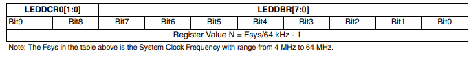
two most significant bits for the frequency value will be added when we turn to the LEDDCR0 register.
when LEDDBR =>
		led_en			<= '1';
		led_cs			<= '1';
		led_exe			<= '0';
		LEDD_ADR		<= "1001";
		DAT_Bits(7 downto 0)	<= "11101101"; --     (   )
		PWM_state_next		<= LEDDONR;
The LEDDONR register records the time in which the LED is active. The documentation contains a table of correspondence to which set of bits belongs to a certain LED burning time.
when LEDDONR =>
		led_en			<= '1';
		led_cs			<= '1';
		led_exe			<= '0';
		LEDD_ADR		<= "1010";
		DAT_Bits(7 downto 0)	<= "00010001"; --    (0.5 c)
The LEDDOFR register contains data for how long the LED is inactive. Exactly the same values as in LEDDONR.
when LEDDOFR =>
		led_en			<= '1';
		led_cs			<= '1';
		led_exe			<= '0';
		LEDD_ADR		<= "1011";
		DAT_Bits(7 downto 0)	<= "00010001"; --    (0.5 c)
		PWM_state_next		<= LEDDBCRR;
LEDDBCRR - data on the duration of LED soft-on.
when LEDDBCRR =>
		led_en			<= '1';
		led_cs			<= '1';
		led_exe			<= '0';
		LEDD_ADR		<= "0101";
		DAT_Bits(7)		<= '1'; --   ()
		DAT_Bits(6)		<= '1'; --
		DAT_Bits(5)		<= '1'; --
		DAT_Bits(4)		<= '0'; -- RESERVED
		DAT_Bits(3 downto 0)	<= "0011"; --   (0.5 )
		PWM_state_next		<= LEDDBCFR;
LEDDBCRR - data on the duration of the LED soft off.
when LEDDBCFR =>
		led_en			<= '1';
		led_cs			<= '1';
		led_exe			<= '0';
		LEDD_ADR		<= "0110";
		DAT_Bits(7)		<= '1'; --   () (disable/enable)
		DAT_Bits(6)		<= '0'; -- PWM Range Extend
		DAT_Bits(5)		<= '1'; --
		DAT_Bits(4)		<= '0'; -- RESERVED
		DAT_Bits(3 downto 0)	<= "0011"; --   (0.5 )
		PWM_state_next		<= LEDDPWRR;
The registers LEDDPWRR, LEDDPWRG and LEDDPWRB record the data on the brightness of the red, blue and green LEDs, respectively. The brightness value is calculated as a percentage by the following formula:
ADC(%) = PulseWidth/256
Therefore, different values of brightness give a mixture of colors, so you can play around and achieve your ideal.
when LEDDPWRR =>
		led_en			<= '1';
		led_cs			<= '1';
		led_exe			<= '0';
		LEDD_ADR		<= "0001";
		DAT_Bits(7 downto 0)	<= "00000001"; -- RED Pulse Width
		PWM_state_next		<= LEDDPWRG;
when LEDDPWRG =>
		led_en			<= '1';
		led_cs			<= '1';
		led_exe			<= '0';
		LEDD_ADR		<= "0010";
		DAT_Bits(7 downto 0)	<= "11111111"; -- GREEN Pulse Width
		PWM_state_next		<= LEDDPWRB;
when LEDDPWRB =>
		led_en 			<= '1';
		led_cs			<= '1';
		led_exe			<= '0';
		LEDD_ADR		<= "0011";
		DAT_Bits(7 downto 0)	<= "00011111"; -- BLUE Pulse Width
		PWM_state_next		<= LEDDCR0;
Well, in the last register LEDDCR0, permission information and two most significant bits of the PWM clock signal frequency are written:
when LEDDCR0 =>
		led_en			<= '1';
		led_cs			<= '1';
		led_exe			<= '0';
		LEDD_ADR		<= "1000";
		DAT_Bits(7)		<= '1'; --   ()
		DAT_Bits(6)		<= '1'; -- Flick Rate Select Bit (125/250 Hz)
		DAT_Bits(5)		<= '0'; --    (1/0)
		DAT_Bits(4) 		<= '0'; --
		DAT_Bits(3)		<= '1'; -- Blinking Sequence Quick Stop Enable Bit
		DAT_Bits(2)		<= '0'; -- PWM Mode Selection Bit
		DAT_Bits(1 downto 0)	<= "10"; --
		PWM_state_next		<= DONE;
Implementation examples
RGB

Purple / White

Summarizing
Well that's all. By changing the parameters, you can achieve a beautiful LED breathing effect with different colors and brightness by changing the values in the LEDDPWRR, LEDDPWRG, LEDDPWRB registers or the RGB driver current value. Below are links to the code on GitHub and all the necessary documentation.
In the future, I plan to test other buns and, if possible, put them here for review.
Evaluation Board User Guide
iCE40 LED Driver Usage Guide
Code