
Previous articles in the series
How does an ordinary computer program work? There is a certain external environment (monitor and keyboard with "mouse" are the most typical representatives of this very environment). The program interacts with them. When debugging, you can make real influences from the external environment, or you can emulate them. Our testers often write all sorts of scripts that just emulate external influences. After that, the log analyzers are launched, which check that the answers are correct on Wednesday.
What if everything is buggy in this computer program? You can set breakpoints and examine a snapshot of the system at the moment when they hit. A slice of the system is the values of the variables. Maybe the states of various mutexes and other synchronization objects. In general, a snapshot of the internal parameters of the debugged system.
When debugging for FPGAs, you can do the same thing. True, if the environment is real, then stopping and studying a section of the system is problematic, albeit possible. As part of the story about Redd, I keep promoting the idea that everything should be simple and fast. We do not design complex systems. We are doing some kind of modules, like what was done in the last article . It is sophisticated, but very, very uncomplicated. In general, we will do its behavioral modeling.
And here the question arises about the external environment. How to simulate it? Models come to our aid. Verilog (as well as VHDL and other similar ones) is quite possible to describe the behavior of anything. We are making a system that works with the ULPI microcircuit ... So, in order to test its operation, there must be something on the other end that behaves exactly like the ULPI. That is, the ULPI model. But this is not enough. Our block reacts to commands from the ALAVON_MM bus. It is this bus that makes the block live. Therefore, we also need to add the bus model AVALON_MM, and this model must be active. It is she who will submit test influences.

Ultimately we have to make just such a system. And then we will be able to record timing diagrams of signals on all of its buses and even inside any of its modules. If an error occurs, we can set breakpoints and examine snapshots of the system to find the enemy. Although, personally, I usually do not set these breakpoints, most often the analysis of timing diagrams is enough. The fact is that signals can be viewed not only interface signals, but any internal ones. Pulling out a dozen or two internal signals on the chart, you can usually guess what is implemented wrong in the logic.
The purpose of today's article is not to talk about what modeling is in general (this is a long story), but to show how to carry out this modeling most quickly. And we will consider this not on a combat mission, but on a simple example. Let's make a very simple test system so that in the next article we will already understand where the legs of a more complex version of it grow from, because when reading it is more convenient not to sit and wonder: “Why does he do this?”, But to know all the basic principles, from which complications already follow ... By the way, recently it turned out that one of my acquaintances, although he possesses the skill of modeling, did not know that the Quartus environment has built-in mechanisms that allow you to do this easily and naturally. He spent much more effort on it than is required. So maybe someone, too, will now learn something new for themselves about the possibilities inherent in Quartus. So,let's get started.
Verilog
People fall into two categories. Those who like to create everything from scratch with their hands and those who like to do it with the mouse. To create everything with your hands is more correct. You can control every action and do everything you know perfectly. But memory is unreliable. If she is doing the same thing all the time, she keeps the details in mind, and if she has to switch between languages all the time, after a month or two she has to remember what needs to be done there. Therefore, work through the option "tinker with the mouse" has the right to exist, if only because of this. Again, if the module being debugged has a dozen or so interface signals, I'm always bored of doing the routine work of re-declaring and forwarding them. Therefore, now we will consider how to make a model using the "mouse". And then - everyone will decide for himself whether this is enough for him, or should he switch to manual work.
So, we want to simulate the module. What is "simulate" is beyond the scope of our cycle, you can write a separate large cycle on this topic. That is, within the framework of this section, we assume that you are familiar with the methodology for developing a model. But then everything needs to be included in the project ... Or not? Oddly enough, you don't even need to create your own project to model a module. We can attach itself as a parasite to any project, without including anything new in it, but only by creating a test suite that will not participate in the main assembly in any way.
For the sake of interest, let's attach to our ULPI project such a funny module on SystemVerilog, written by me specifically for illustration and having nothing to do with the developed analyzer. Just some time ago I had a lot of messing around with calculating checksums, so it came to my head.
module sum(
input         clk,
input [7:0]   data,
input         we,
input         sof,
output [15:0] sum
);

logic [15:0] temp;

always @ (posedge clk)
begin
     if (we)
     begin
         if (sof)
             temp <= data;
         else
             temp <= temp + data;
     end
end

//   -
//assign sum = (~temp)+1;
//    :
assign sum = temp;
endmodule
It can be seen that data comes to it via a bus, which is very remotely reminiscent of AVALON_MM, and is simply output in parallel code.
Let's put the resulting file in the directory with our project, but we will not include it in the project in Quartus. Instead, we'll create a test suite specifically for it. To do this, select the menu item Assignments—> Settings:

and in the tree that appears, look for the item EDA Tools Settings—> Simulation:

By the way, about the type of simulation highlighted by the green frame. Perhaps someone remembers that in the first articles I said that when creating a project, purely out of habit, I choose ModelSim Altera? It was the very gun on the stage that sooner or later had to fire. However, if you did not select a modeling type when creating the project, you can select or change it here.
We continue to create a test suite. Switch the radio button to Compile test bench (by the way, how does this term translate beautifully into Russian? I can't bring myself to write "test bench", since I don't see any bench) and press the Test Benches button :

In the dialog that opens, press New :
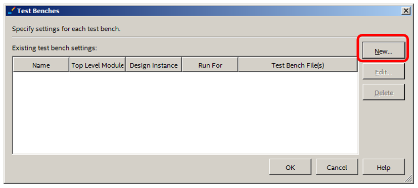
If to do test case manually, you can fill in the fields in one pass. But since we do everything with the "mouse", now we fill in only part of the fields, and we will fill in the rest later. In the Test bench name fieldI typed in the word Parazit (how else to call a test that just parasitizes on the project?). The word Parazit has been filled in automatically below it. We will not change it now, but in the future we still have to do it. Also, using the "..." button, I selected the sum.sv file with the code of the adder to be debugged, and then, using the Add button , pushed it into the list of test files. For now, that's it. Closing the dialog ...

Next, we will continue to form the test in the ModelSim environment. To do this, select the Tools—> Run Simulation Tools—> RTL Simulation menu item:

The ModelSim window opens. Perhaps errors will be found in the Verilog code, then you need to close ModelSim, correct errors, and reopen. But sooner or later, the list of mistakes will become purely organizational. It looks like this to me:
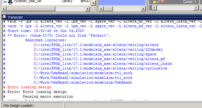
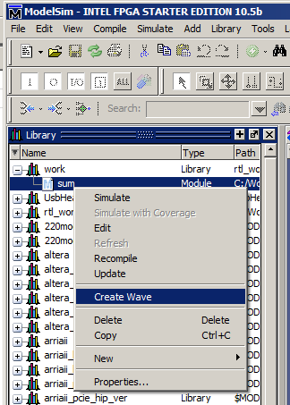
No top-level module found. This is normal. We haven't created it simply yet. Therefore, we go to work in the list of libraries and open it. Here it is, our adder.

Hover over it, press the right mouse button and select the Create Wave menu item. This is all so boring in the text, if I were shooting a video, the whole process would take tens of seconds, so don't be alarmed, but watch your hands further. So, Create Wave ...
The module interface signals have automatically moved to the chart:
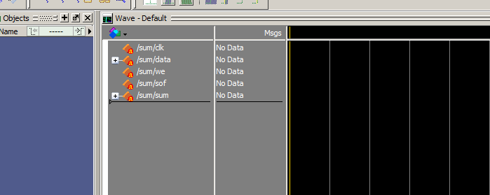
It is necessary to assign a value to one of them. It doesn't matter which one, it is important to appoint. Quartus' very old modeling environment was good at generating clock signals. Alas, it was withdrawn from the delivery a long time ago, since they began to attach ModelSim, and here everything is not so beautiful with something like that. I didn't see the point of generating a generator here, so I won't even show it. So ... Well, let's set the line we to zero. We aim at the signal, press the right button, select the menu item Edit—> Wave Editor—> Create / Modify WaveForm.

In the dialog that appears, select Constant . And at the same time we will change the time, say, by 100 microseconds:
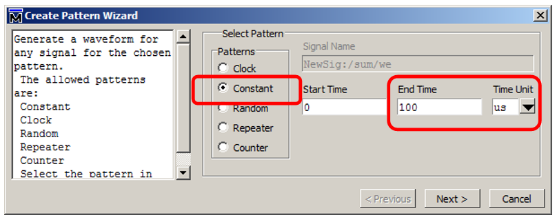
Next, we indicate the value 0:

We have created the minimum required data set, and the rest will be easier to do with pens. We export the file. To do this, select the menu item File—> Export—> Waveform:

Select the file type Verilog Testbench (by the way, it’s a pity that it’s not SystemVerilog, but in the future it will be possible to correct it with pens). We also set the file name. I named it parazit_tb , following the "why not?"

That's it, ModelSim can be closed, while the temporary house does not need to be saved.
What to do with the model next
Here is such a crooked, but still a ready-made Verilog file, the system created for us:
`timescale 1ns / 1ns
module parazit_tb  ;

  reg    sof   ;
  reg    we   ;
  wire  [15:0]  sum   ;
  reg  [7:0]  data   ;
  reg    clk   ;
  sum
   DUT  (
       .sof (sof ) ,
      .we (we ) ,
      .sum (sum ) ,
      .data (data ) ,
      .clk (clk ) );


// "Constant Pattern"
// Start Time = 0 ns, End Time = 100 us, Period = 0 ns
  initial
  begin
  end

  initial
	#0 $stop;
endmodule
Automation saved us from writing building blocks. Moreover, if there were more interface signals, the automation would obediently register and connect all the circuits. Personally, when I manually create test suites, it is the process of describing signals and their forwarding that is depressing. Now, in this file, we will now create an environment model that will affect the debugged sum module .
As you can see, there is no sense in setting the constants made by the oscillator. But all the same, all the circuits have been created, the module to be tested is connected, even the initial section has been created. Let's refine the code. First, we will remove the breakpoint by removing the lines:
  initial
	#0 $stop;
Next, we will add a clock generator model (how I miss a wonderful generator that the old Quartus made! There you could set the frequency in megahertz and not think about recalculating it into a period, and even more so a half-period).
  always
  begin
      clk = 0;
      #5;
      clk = 1;
      #5;
  end
Now we need to send some data bytes. The easiest way to do this is right in the initial section , but if I write each bus access phase there, the code in this section will become confusing. Therefore, I will do the following task (it is she who acts as a tire model):
task SendByte (input reg[7:0] D);
    begin
        data = D;
        we = 1;
        @(posedge clk);
        #1
        we = 0;
   end
endtask
Well, I'll write the purpose of the constants and the call of cycles for working with the bus in the initial block . Let me remind you that the record type # 123 means "wait 123 units of time". We have it in nanoseconds. I also remind you that since the assignments are sequential, we use the "equal" operation, not the "arrow". So, we have the following main testing code:
Watch here
  initial
  begin
     sof = 0;
     we = 0;
     data = 0;
     #13;
     //
     sof = 1;
     SendByte (1);
     //
     sof = 0;
     SendByte (5);
     SendByte (1);
     //
     #20;
     SendByte (1);
  end
In total, our complete module code looks like this:
View the complete module code.
`timescale 1ns / 1ns
module parazit_tb  ;

  reg    sof   ;
  reg    we   ;
  wire  [15:0]  sum   ;
  reg  [7:0]  data   ;
  reg    clk   ;
  sum
   DUT  (
       .sof (sof ) ,
      .we (we ) ,
      .sum (sum ) ,
      .data (data ) ,
      .clk (clk ) );


  always
  begin
      clk = 0;
      #5;
      clk = 1;
      #5;
  end

task SendByte (input reg[7:0] D);
    begin
        data = D;
        we = 1;
        @(posedge clk);
        #1
        we = 0;
   end
endtask

// "Constant Pattern"
// Start Time = 0 ns, End Time = 100 us, Period = 0 ns
  initial
  begin
     sof = 0;
     we = 0;
     data = 0;
     #13;
     //
     sof = 1;
     SendByte (1);
     //
     sof = 0;
     SendByte (5);
     SendByte (1);
     //
     #20;
     SendByte (1);
  end

endmodule
Completing test case preparation
It's time to add this text to the test suite. To do this, go to the dialog already known to us.But

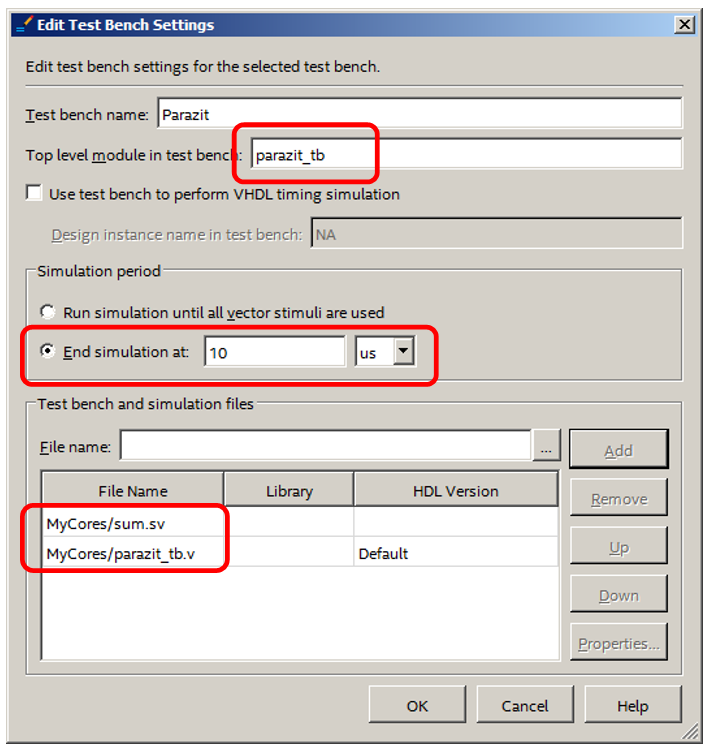
now we do not create our set, but select it from the list. In the future, the list will grow as the sets are added ... Having selected, press the Edit button. I made three edits to the settings:
- Added the parazit_tb.v file to the list.
- Since in the parazit_tb.v file , the top-level module has the name parazit_tb (you can make sure by looking at the source from the previous section), I entered this name in the Top level module in test bench line .
- I said to run the simulation for 10 microseconds and then pause. If anything, I will do it by pressing the manual control buttons.
Total
We close everything. Run ModelSim again. We see that everything is working correctly. The data comes in and is counted in the amount. If there is no data on the clock ( we is zero), the amount does not increase.

How to use the modeling environment itself is a topic for several articles. And rather in video format. But in general, we got acquainted with the method of quickly preparing and running tests in the Verilog language from the Quartus environment.
Now that we know how to quickly run the simulation, we can sketch out an environment model for our USB analyzer head and test its operation. At the same time, we did not memorize a single ModelSim spell, since Quartus allows you to configure everything using the "mouse". He generates all the necessary scripts himself and calls the ModelSim environment himself. We also created the base for the model in automatic mode, although we then had to manually modify it.
Alas and ah. One of the elements of the external environment is the ULPI module. To develop its model on your own, you must, firstly, carefully understand the logic of the operation of that microcircuit. And in the previous article I said that it is very tricky. And, secondly, you need to spend a lot of time developing the model code. And the elimination of errors in it ... It is clear that it is easier to find something ready-made. But the ready-made model was found only in the SystemC language. Therefore, in the next article, we will learn to model a system using this language.