Creation of a layout.
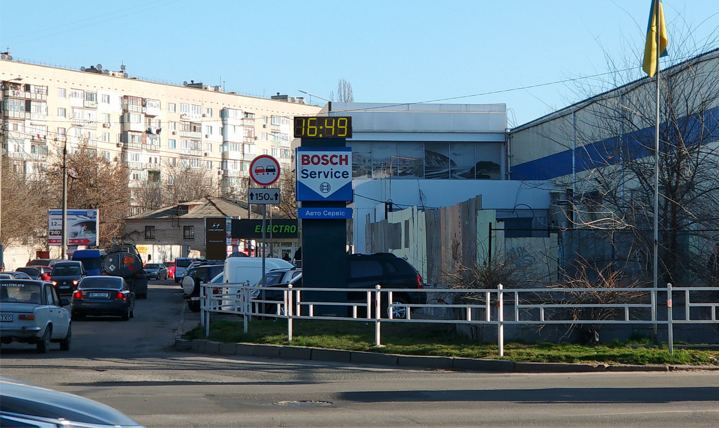
After preliminary clarification - what, how and why - "the Client needs", usually a visit to the site should be carried out in order to photograph the place of the proposed installation. Preferably in good weather, with adequate lighting. It is important to take the photo at as much right angle as possible. It is also necessary so that some elements with a known size (window, door, road sign) get into the frame, this will be needed in the future to bind the coordinate (scale) grid.
Then - a drawing of the proposed product is created. Usually - a couple of options, because too large “space of choice”, as experience shows, greatly complicates the process “The client has decided”. The drawing is painted in the color of the expected glow of the LEDs.
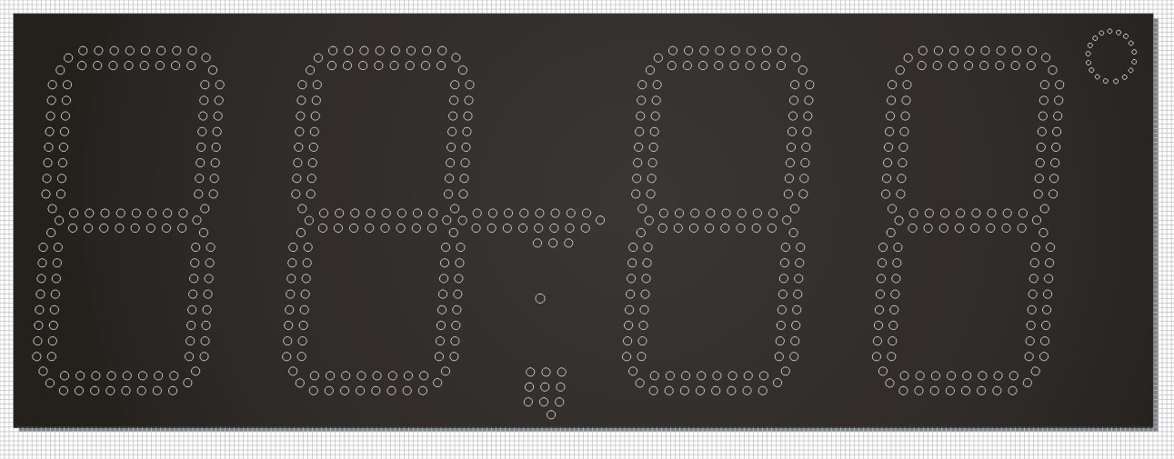
The resulting image is superimposed on the photo of the intended installation site, observing the scale and proportions (this is exactly what the snap to the grid was needed for). The final image is the so-called. "Photoview" - that is, a photorealistic image of a still NOT existing object, so to speak, "in real conditions." Of course - bother with shadows, ultra-realism, and so on. - we won't, "they don't pay for it."
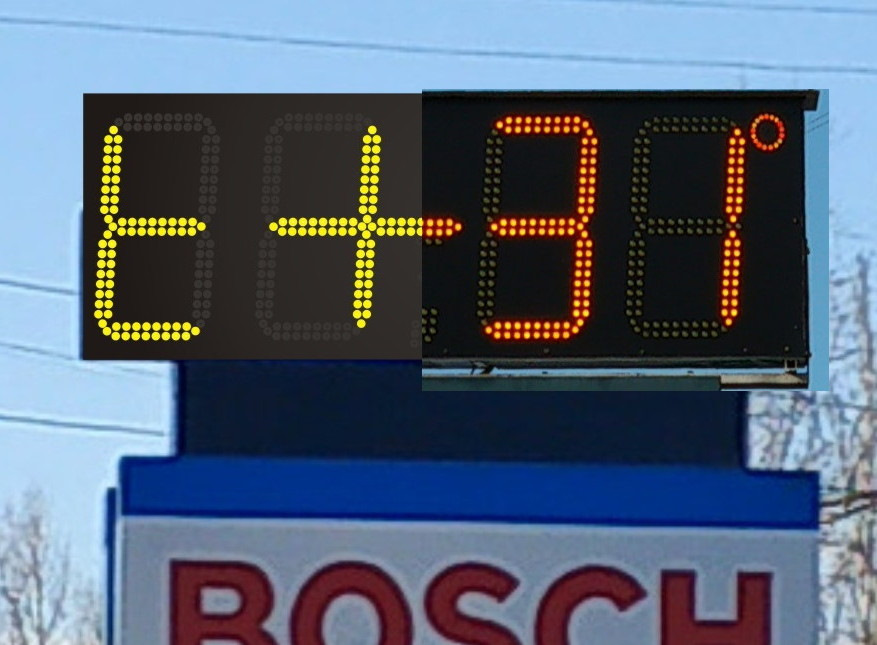
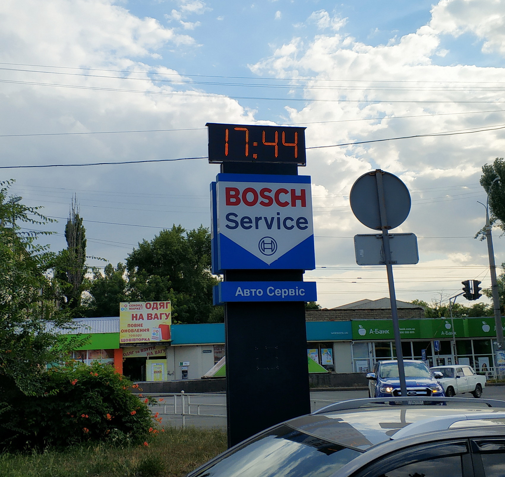
How much the photo view differs from the already actually manufactured and mounted product can be seen in this picture.
After the approval of the layout by the Customer, the drawing is sent to the milling cutter, a substrate is formed, so to speak. Which is just a panel with holes ...
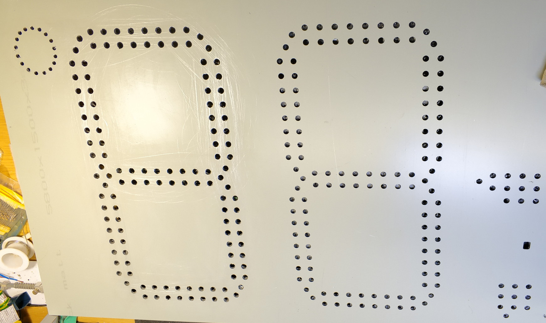
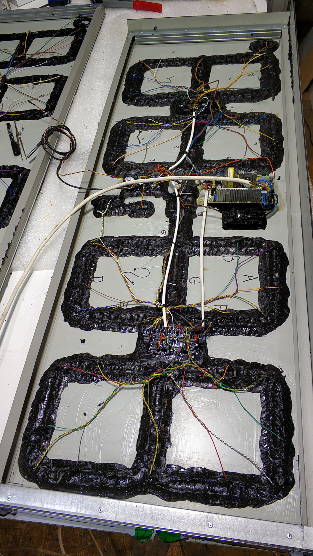
Output LEDs are inserted into the substrate in a certain order, their legs are connected to the required "matrix"
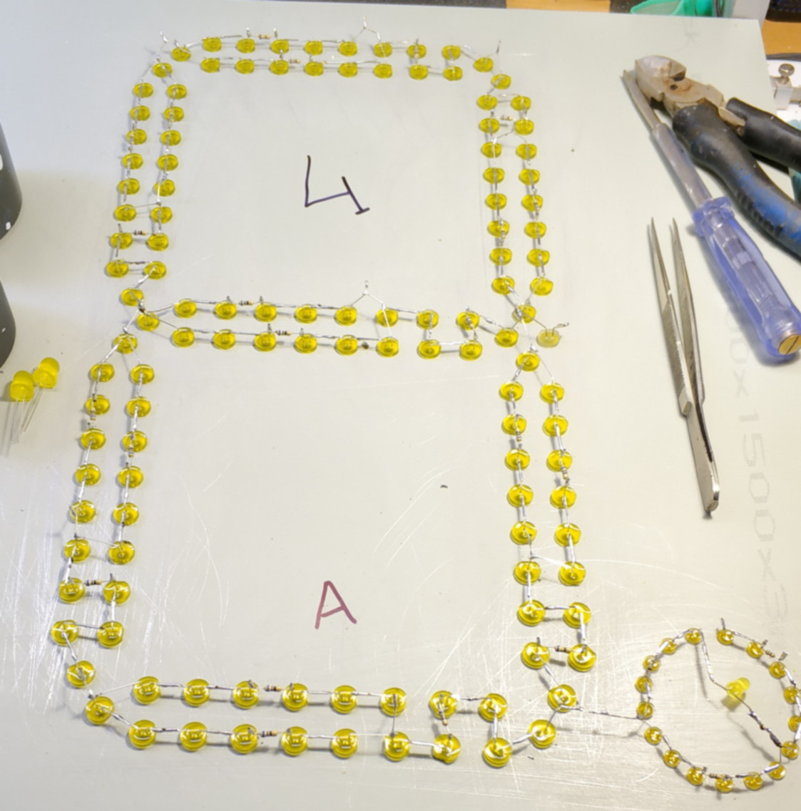
The entire matrix is filled with a compound, which will further play the role of elastic vibration and moisture protection, as well as keep the LEDs from falling out into the case.
We make boards, usually several so-called. "Driver" and "processor" (which will house the control microcontroller, clock generator microcircuit, backup battery, buzzer, thermometer interfaces, IR receiver (commands from the wireless remote control).
Boards are "assembled" (components are soldered), it is convenient to use SMD ( leadless components), smaller dimensions, no need to form leads, faster installation ...
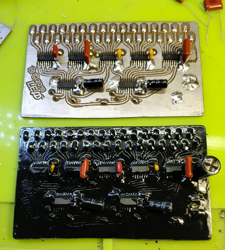
Particular attention is paid to "earthen" circuits, even the paths of current passage through the copper coating of the boards, because with currents even in a couple of Amperes (a clock - that = a low-voltage device, which means that relatively large currents are needed to achieve any significant power) - "amplification »The path of the large currents.
Already assembled (and - tested - better right away, then it will be very inconvenient) boards are covered with a protective layer of paint or varnish (the product is still outdoor) and after drying - they are mounted in the case, you can simply glue them to the display panels (estimated "lifetime "- does NOT imply dismantling).
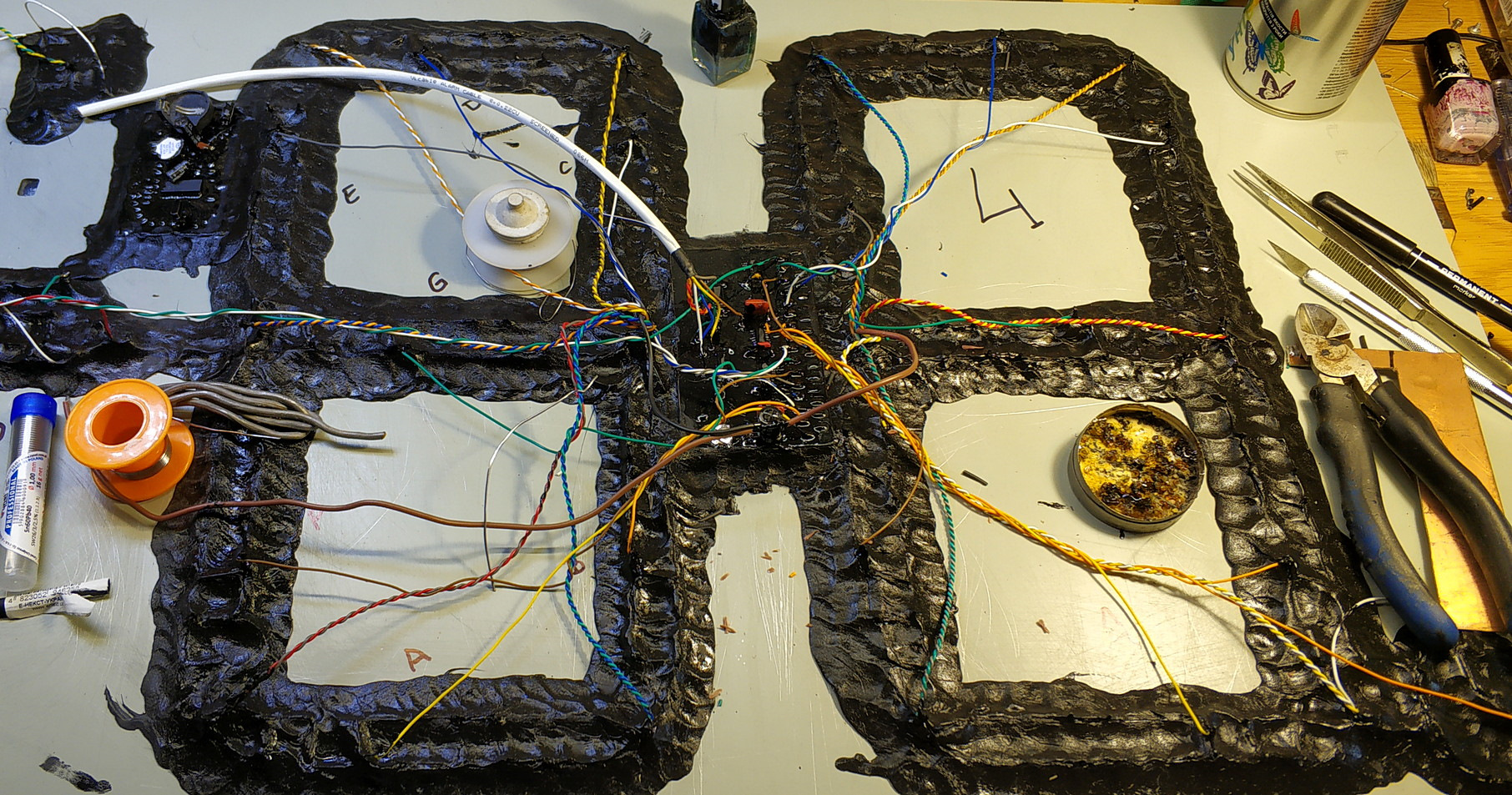
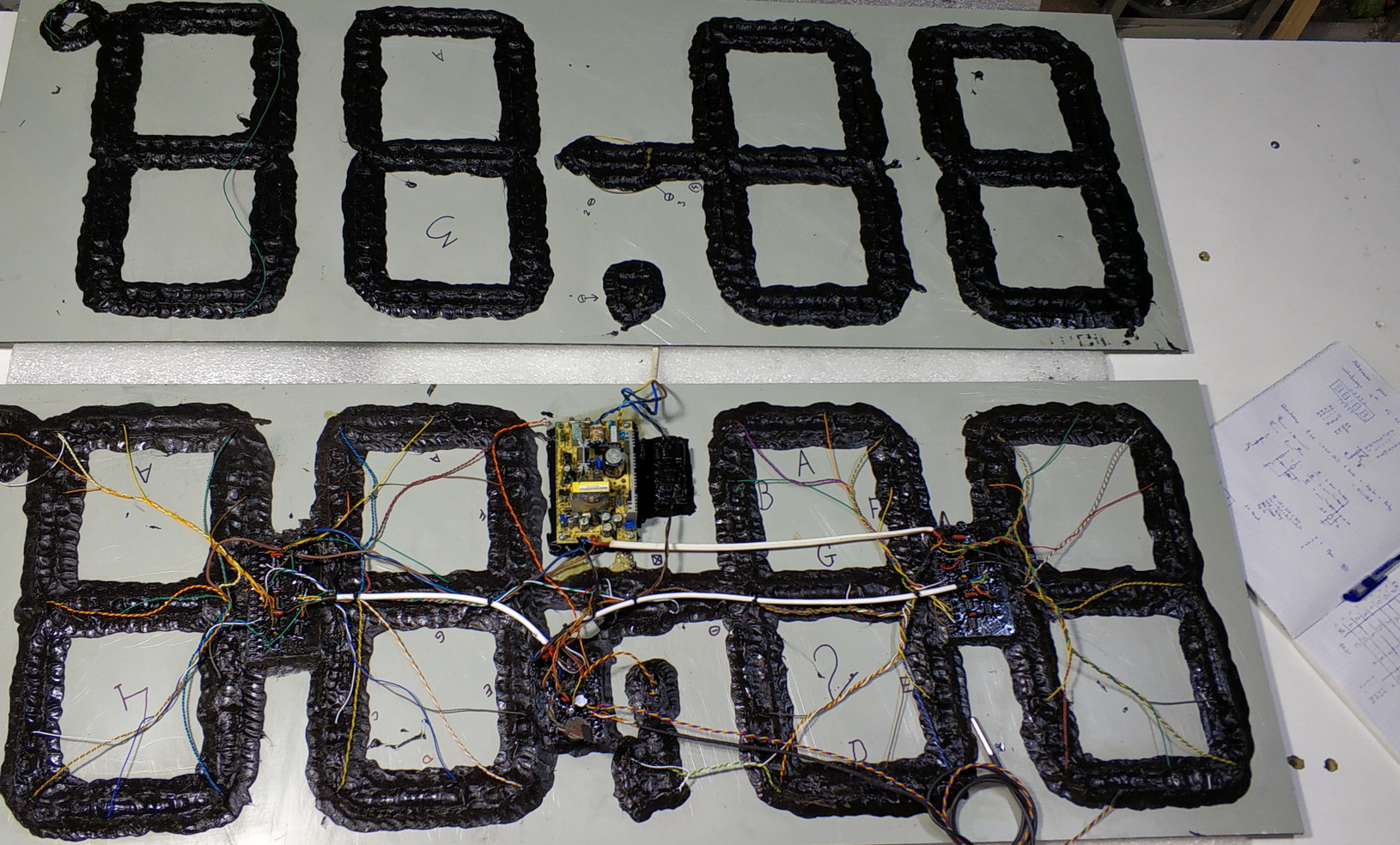
Connections of the actual LED matrix pins and driver boards are made.
A place is being prepared for mounting power supplies - additional insulation will be required here ...
The processor board, IR receiver, board-to-board connections are mounted ...
The reverse side is made in the same way (clock = "double-sided"!). Power frames are inserted ... Everything is checked, the sides, the lid are glued, special attention should be paid to sealing the seams and drainage ...
Further - the installation itself!
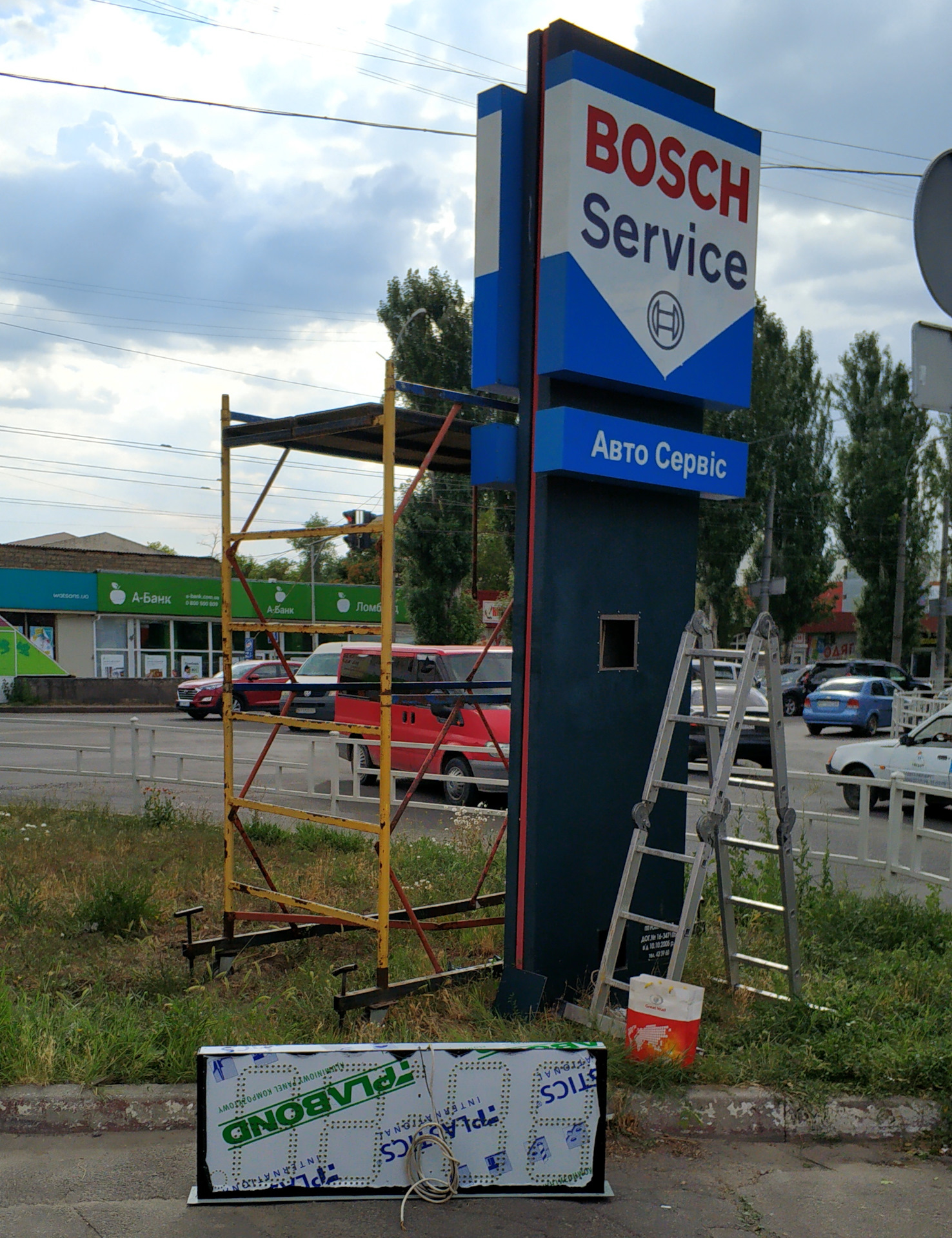
Actually - installation, final check and adjustment.
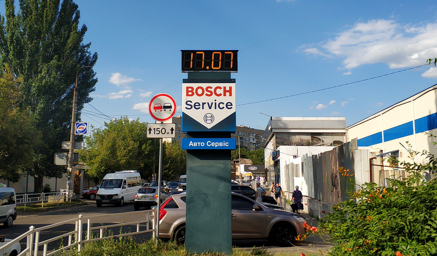
READY
View from one side:
And - from the other:
You can watch it live on video:
Thank you for your attention!