The very same interference
During my internship at the factory, I decided to take the converter handkerchief with me and look at the oscilloscope what actually happens at the output. To my surprise, the interference was not at the output of the converter, but in principle on the power supply. When the PWM level changed from low to high, a strong voltage drop was observed along the 5 volt line, by about 1-2 volts, and when the state changed from high to low, there was a jump up by about 1.5 - 2.5 volts. And all these pulsations were at the frequency of the PWM. When powered directly from the battery, nothing really changed. At this point, I decided to never again use such types of converters in my devices (Specifically, if you need to increase the voltage more than 2 times). There were also recommendations to replace the field-effect transistor with a bipolar one,but my attempts to find something with a high gain (about 300), in an smd package and with a voltage of about 450-500 volts were unsuccessful, this refers to the use of a field-effect transistor, which opens fully at 10 volts.
Transferring firmware to a live device
To be honest, I didn't think that I would run into problems, because everything worked well on the breadboard (and when I made a board for the first version on a seven-segment display, everything was fine), and there were no problems that arose after the firmware.
In fact, only the screen and the menu worked, but the pwm, ADC, timers and interrupts refused to work. Again, everything worked well on arduin. As a result, by rearranging the initialization of the timers, I managed to achieve normal operation of the device.
The need to remove the arduino framework. Yes, arduino is bad, which I have already understood more than once, and in my code at the moment only the millis and micros methods are used from this framework. I am trying to overcome all this, and some successes have already been achieved. Also, arduina still lives in my code because of the display library, which I already defeated without using arduina, and soon it will go away altogether. any amount of memory I need will add. Also, using C ++ instead of C in microcontroller programming is not the best practice, so this point will also need to be redone.
What's new in the firmware?
From the main thing that was added / fixed:
- Removed delays from the sound indication, which greatly increased the speed and accuracy of readings.
- , .
- . .
- .
- , . , .
- .
- , ( 30 255 /).
- . , , .

- ( ) .

What's changed on the PCB?
- The boost converter and 3.3 volt linear converter were connected directly from the battery.
- The ratings of the voltage divider on the battery have been changed from 10 kΩ to 220 kΩ.
- The field-effect transistor was moved from the emitter amplifier to a voltage divider to remove the voltage from the battery.
- Extra pull-up resistor removed.
- Some dip components are replaced with smd.
What's in the firmware?
In addition to what I listed earlier, the firmware contains:
- Three operating modes: search, measurement (as in the Pripyat dosimeter) and particles / s
- Calculation of the measurement error in the search mode. There is both an advanced algorithm and a simpler one. Selected in the config file.
- Settings for: sbm-20, sbm-19, beta-1-1
- Plotting (Yes, not new, but it looks good).
- Sleep mode (Reduced power consumption, the device is turned on either by holding the button, or by alarm). Not completed at the moment.
- Sound and light indication and its setting
- Russian and English (Installed in the configuration with firmware)
The configuration file describes what can be disabled and how much memory it will free.
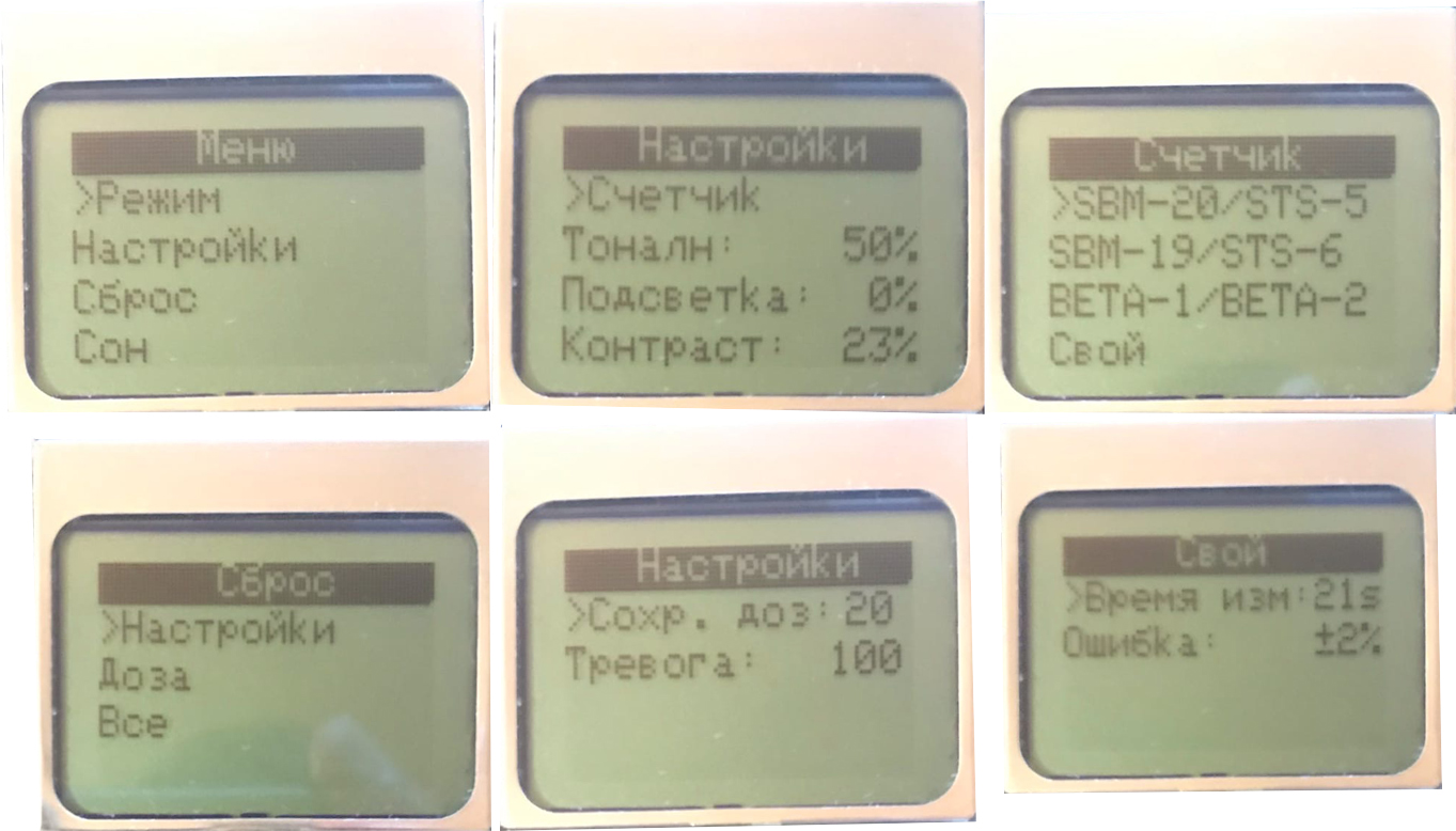
Navigation and menus
The device is controlled by two buttons. The left one is reset and the right one is set.
In order to enter the menu, you must hold both for 1 second.
Navigation through the menu is done by short pressing of the buttons. Selecting the required item - holding the set button. Cancel or Back - hold the reset button.
The menu implements most of what I wanted, but if it were not for the memory and port restrictions of gpio, then the ability to build maps (sd + gnss) would be added.
Search mode
I think this mode does not require a detailed explanation. Essentially, it shows the current value in micro roentgens per hour, and changes the range depending on the current value. The readings are averaged not over the median, but simply the sum of measurements over time, and can be turned on by pressing the right button. In the upper right corner, the battery charge is shown, the statistical error is slightly lower and the accumulated dose is even lower.
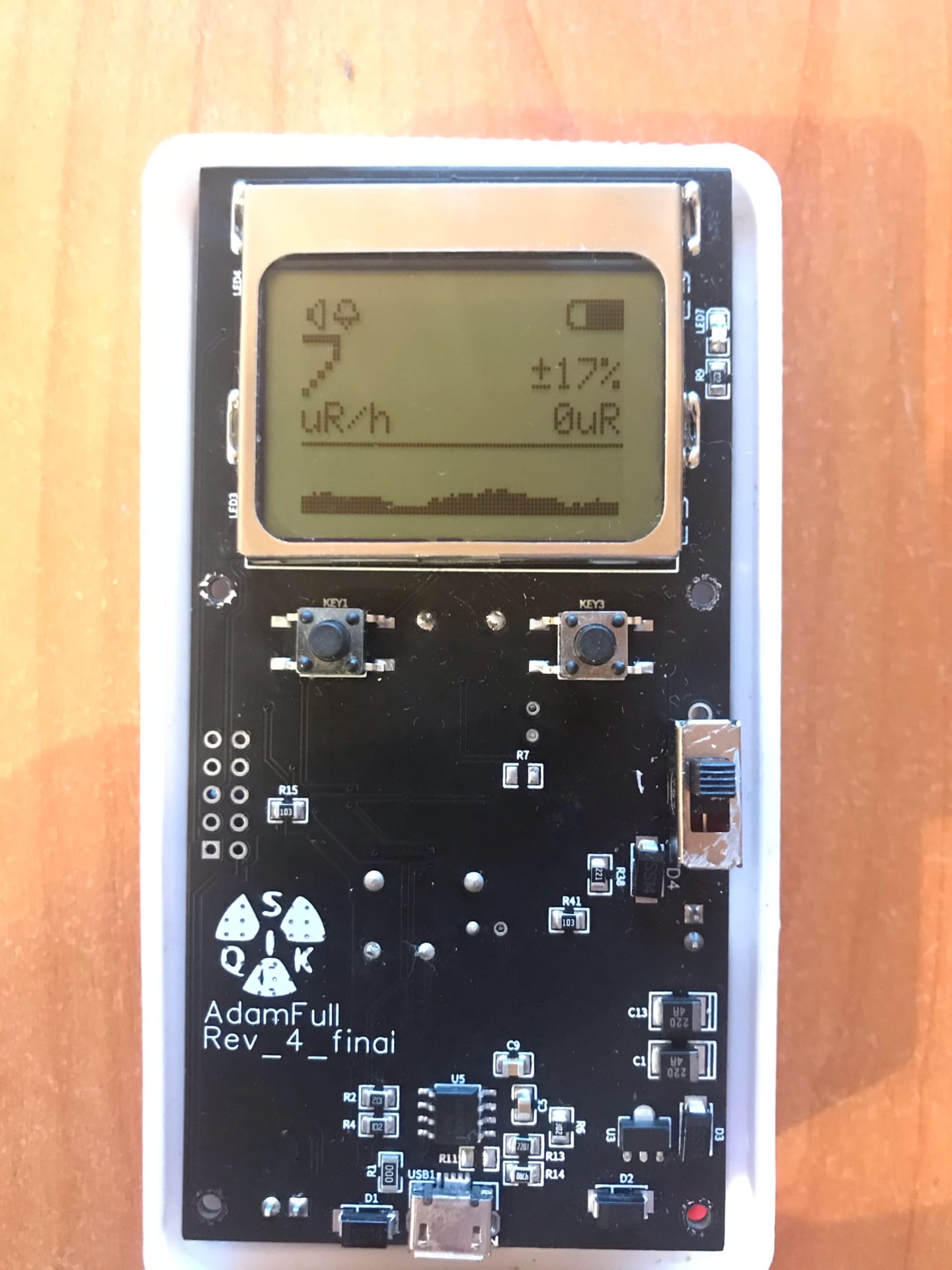
Also in this mode, you can turn off the sound and alarm. To mute the sound, press the left button once, and to mute the alarm, either press the left button during the alarm, or hold the left button.

Activity measurement mode
Customizable mode, both in time and in the number of measurements. The maximum measurement time that can be set is 120 minutes, and the number of measurements is 2. In essence, it automates the measurement process available in the Pripyat dosimeter. The second is subtracted from the first dimension and the modulus is taken from this, as a result, the number of fixed particles for the specified time is obtained. It can be used in different ways, both for measuring products and for separating individual particles, measuring first, let's say first with an alpha filter, and then without it, etc.

A similar regime was implemented by many who assembled their own dosimeters, and I am no exception.
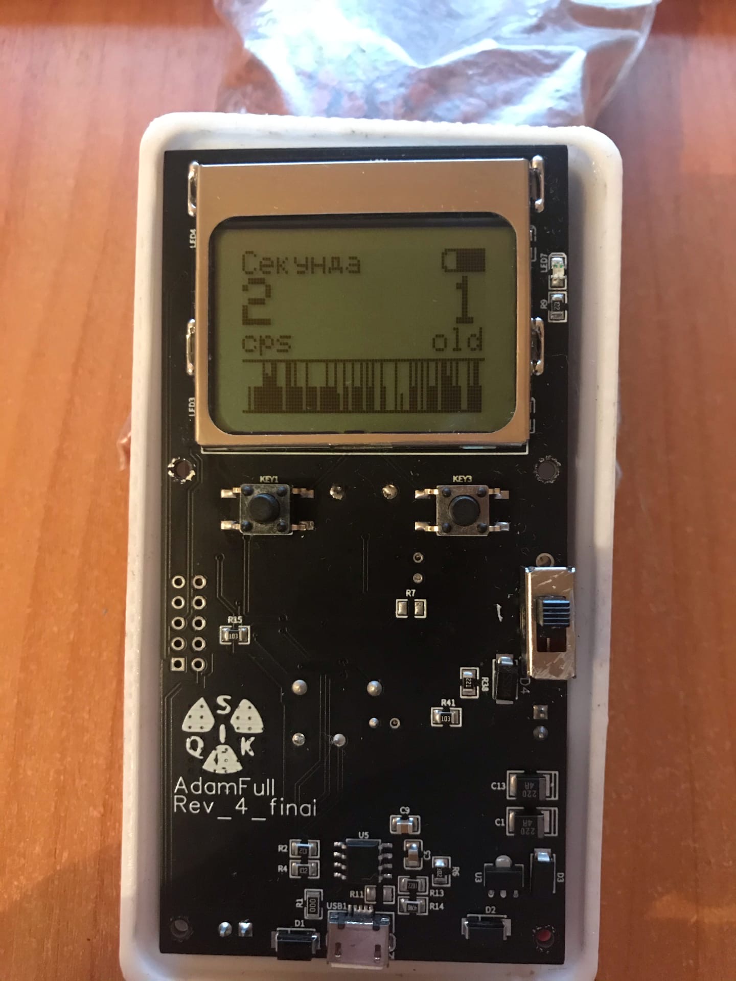
Second metering mode
This mode shows the number of particles per second, no matter how logical it sounds. The number of particles from the previous measurement is displayed on the right side of the screen. The graph is built in the same way as in the search mode.
Housing
At the moment, the following body was developed in the fusion 360 program.
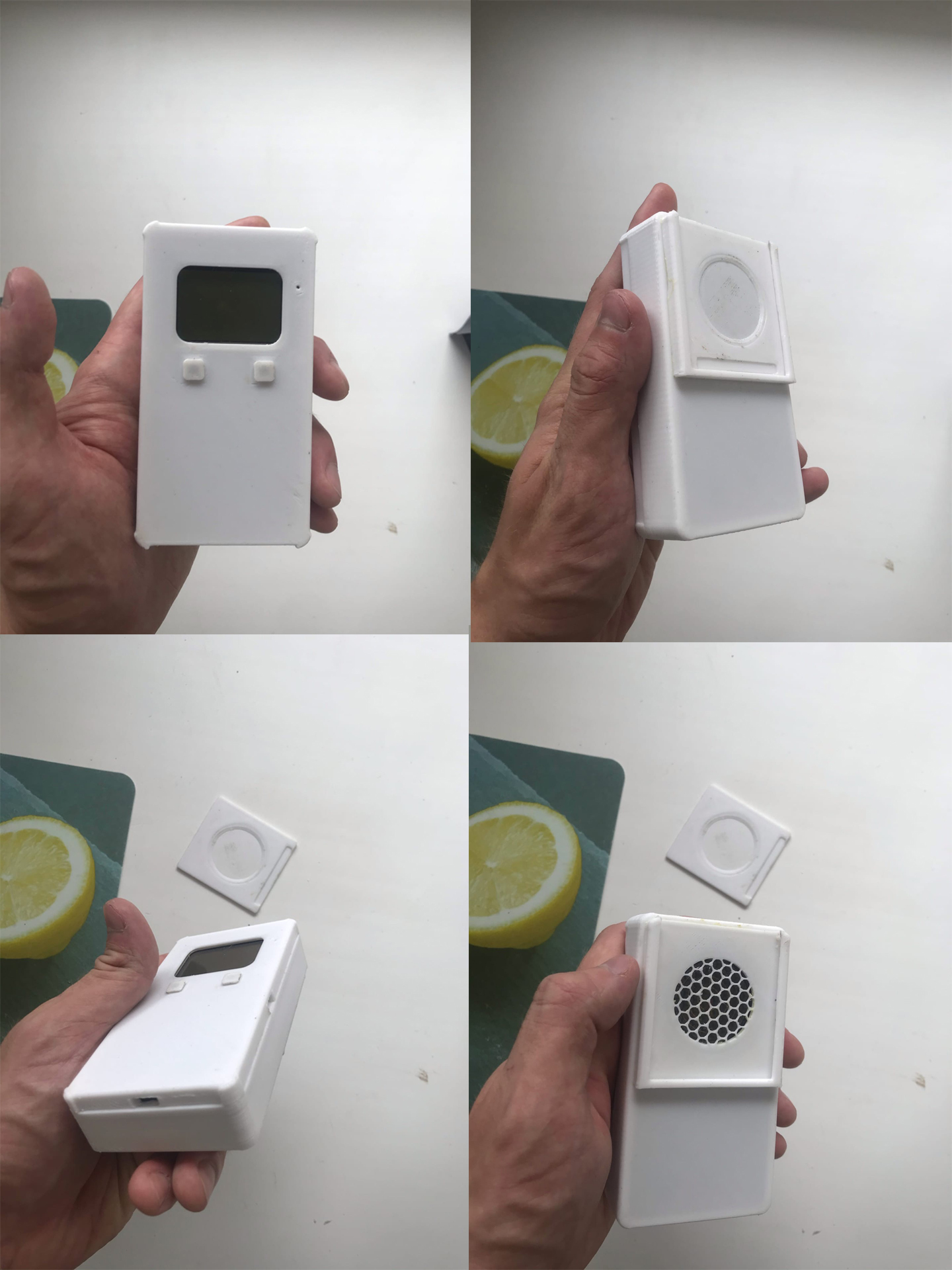
The body was made for the Beta-1-1 sensor and with the expectation that it will be printed on a 3D printer. I will post models in stl format later.
The holes for fixing the board are made for fusing there the sleeves for the M2 screws.
Instrument problems
The main problem, as noted in the comments to the last part, is that the problem with false alarms is essentially not solved, but, let's say, "covered with tape," and yes, I completely agree with that. I tried to fight it in other ways, but it did not give very good results. I did power directly from the battery, this partially reduced the range of power ripples, put additional electrolytic capacitors for power supply (I put it even at 10000mkf, it also did not help), well, ceramics also did not solve the problem. I voiced my conclusion about this, I will no longer repeat such mistakes. The transformer will come out a little more expensive (so for 250 rubles apiece, compared to 45 for inductance.), But there will be much less trouble with it.
Due to the fact that the stable generation is at 4 kHz, a weak but annoying squeak is heard in silence. You can't go into reconnaissance with this device.
The voltage converter is also a major failure. I decided to do it on it, only because of the availability of the inductor, but I did not immediately think about the rest.
But despite the shortcomings, as for me, he completely fulfills the tasks that I wanted. For a household dosimeter, I think it will do, for a professional one it is enough.
Power consumption of the device
The device discharges a 600 mAh battery in 12-14 hours of active use (discharge up to 3.6). Most likely, the capacity of the battery is no longer 600 mAh, because he stood in an electronic cigarette for a year and a half.
What's next?
In the future, I will finish the firmware of the current device, and I will start doing the same on stm32, but taking into account all my mistakes. I also want to add support for sd cards, gnss, replace the screen with 1202, and it is possible to make power from batteries if I do not find a good dc-dc step-down microcircuit.
Addition
I forgot to say. Since the device cannot record more than 1000 particles (in fact, a little less) per second, a counter will be added to the program to check that the measurement limit has been reached. At the moment it is implemented like this. If the background value is at a value of 0 μR / h for more than 3 seconds, an alarm is triggered and the over-range flag is turned on.
Link to the previous part