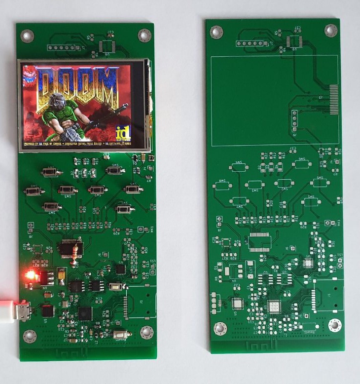
The main goal was to try to unsolder the esp32d0wdq6 chip. Not the finished module itself, but a separate microcircuit with a separate Flash and PSRAM. How it is done and works, with video demos, read and look further
Here you can read about the first iteration of the board
Boot
Boot Log
rst:0x1 (POWERON_RESET),boot:0x13 (SPI_FAST_FLASH_BOOT)
configsip: 0, SPIWP:0xee
clk_drv:0x00,q_drv:0x00,d_drv:0x00,cs0_drv:0x00,hd_drv:0x00,wp_drv:0x00
mode:DIO, clock div:2
load:0x3fff0030,len:4
load:0x3fff0034,len:7076
load:0x40078000,len:14600
load:0x40080400,len:4160
0x40080400: _init at ??:?
entry 0x40080684
I (28) boot: ESP-IDF v4.2-dev-2243-gcf056a7d0-dirty 2nd stage bootloader
I (29) boot: compile time 18:51:57
I (30) boot: chip revision: 1
I (33) boot_comm: chip revision: 1, min. bootloader chip revision: 0
I (52) boot.esp32: SPI Speed: 40MHz
I (53) boot.esp32: SPI Mode: DIO
I (53) boot.esp32: SPI Flash Size: 8MB
I (56) boot: Enabling RNG early entropy source…
I (62) boot: Partition Table:
I (65) boot: ## Label Usage Type ST Offset Length
I (73) boot: 0 factory factory app 00 00 00010000 000e8000
I (80) boot: 1 wifidata WiFi data 01 02 000fc000 00004000
I (88) boot: 2 wad unknown 42 06 00100000 004f4000
I (95) boot: End of partition table
I (99) boot_comm: chip revision: 1, min. application chip revision: 0
I (106) esp_image: segment 0: paddr=0x00010020 vaddr=0x3f400020 size=0x38f98 (233368) map
I (216) esp_image: segment 1: paddr=0x00048fc0 vaddr=0x3ffb0000 size=0x07058 ( 28760) load
I (230) esp_image: segment 2: paddr=0x00050020 vaddr=0x400d0020 size=0x86370 (549744) map
0x400d0020: _stext at ??:?
I (468) esp_image: segment 3: paddr=0x000d6398 vaddr=0x3ffb7058 size=0x04ec4 ( 20164) load
I (478) esp_image: segment 4: paddr=0x000db264 vaddr=0x40080000 size=0x00404 ( 1028) load
0x40080000: _WindowOverflow4 at /esp/v3.3.2/esp-idf/components/freertos/xtensa/xtensa_vectors.S:1730
I (479) esp_image: segment 5: paddr=0x000db670 vaddr=0x40080404 size=0x12b7c ( 76668) load
I (538) boot: Loaded app from partition at offset 0x10000
I (538) boot: Disabling RNG early entropy source…
I (549) psram: This chip is ESP32-D0WD
I (551) spiram: Found 64MBit SPI RAM device
I (551) spiram: SPI RAM mode: flash 40m sram 40m
I (555) spiram: PSRAM initialized, cache is in low/high (2-core) mode.
I (562) cpu_start: Pro cpu up.
I (566) cpu_start: Starting app cpu, entry point is 0x4008191c
0x4008191c: start_cpu0_default at /esp/v3.3.2/esp-idf/components/esp32/cpu_start.c:466
I (0) cpu_start: App cpu up.
I (1454) spiram: SPI SRAM memory test OK
I (1462) cpu_start: Pro cpu start user code
I (1462) cpu_start: Application information:
I (1462) cpu_start: Project name: esp32_doom
I (1466) cpu_start: App version: 085f21b-dirty
I (1472) cpu_start: Compile time: Jul 26 2020 18:51:49
I (1478) cpu_start: ELF file SHA256: 9166eca39a0109f9…
I (1484) cpu_start: ESP-IDF: v4.2-dev-2243-gcf056a7d0-dirty
I (1491) heap_init: Initializing. RAM available for dynamic allocation:
I (1498) heap_init: At 3FFAE6E0 len 00001920 (6 KiB): DRAM
I (1504) heap_init: At 3FFCF628 len 000109D8 (66 KiB): DRAM
I (1511) heap_init: At 3FFE0440 len 00003AE0 (14 KiB): D/IRAM
I (1517) heap_init: At 3FFE4350 len 0001BCB0 (111 KiB): D/IRAM
I (1524) heap_init: At 40092F80 len 0000D080 (52 KiB): IRAM
I (1530) spiram: Adding pool of 4096K of external SPI memory to heap allocator
I (1539) spi_flash: detected chip: generic
I (1543) spi_flash: flash io: dio
I (1548) cpu_start: Starting scheduler on PRO CPU.
I (0) cpu_start: Starting scheduler on APP CPU.
I (1557) spiram: Reserving pool of 32K of internal memory for DMA/internal allocations
KiCad PCB
In KiCad, it seemed to me easier. For my taste, of course. Slightly different than Eagle Autodesk. The main plus is that there is no limit on the amount of fees if you do not want to pay for a license. Let me remind you that Eagle has a size limit of 100x80mm for free development. If the fee is more you have to pay an annual license. In my opinion, there is also a limit on the number of layers

I could not see 3D View in Eagle. It is necessary to install Eagle Fusion 360. In Kicad this is a separate menu item. Although I may not have looked there. In general, we can say completely switched to KiCad.
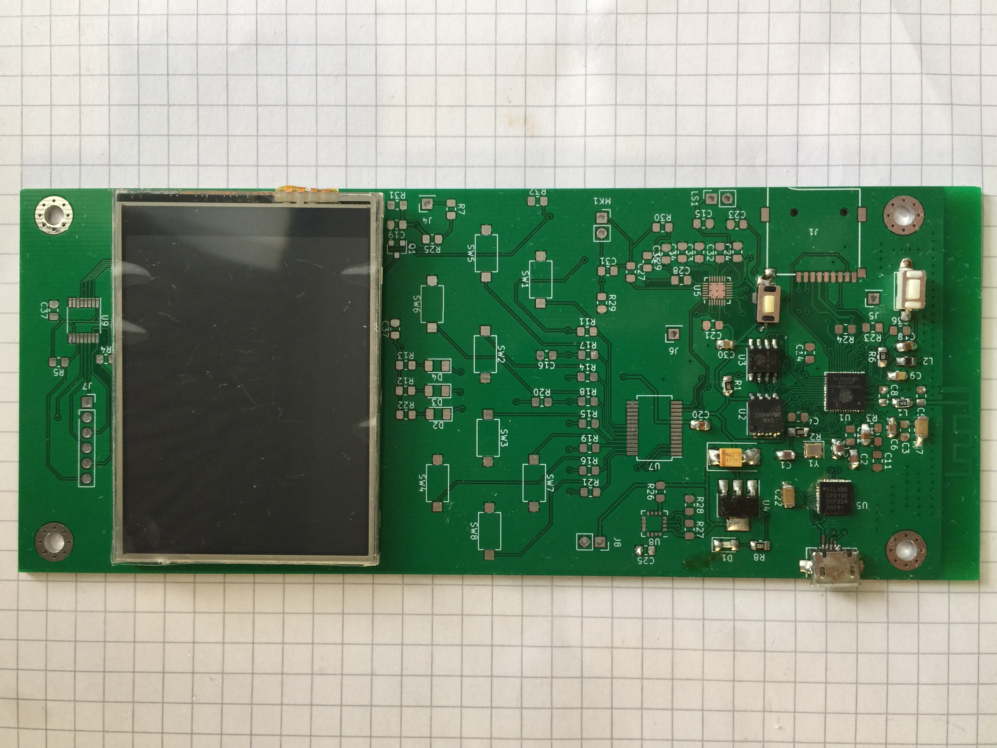
Divided everything into modules, leaving on the main page what is directly related to ESP32. The chip itself and the memory

Errors
I drew the board in pauses. As a result, I forgot to output GPIO0. I brought it to an external DAC as MCCLK, but I forgot to bring it to the boot mode button. I had to rip off the varnish from the soldering track for the button output. Also, the resistor in the quartz circuit was set to XTAL_N and in the manual it is necessary to XTAL_P. I hung up a resistor of several ohms, but it was possible to throw a jumper. The
Address and Reset resistors for the MCP23017 did not divorce. The chip can be set to the I2C address with three pins. 0x20h when all three pins are on the ground. All because I did not specify FootPrint

I did not pay attention to the error
Error: Cannot add R10 (no footprint assigned).
Error: Cannot add R9 (no footprint assigned)
Confused i2C for ES8374. Sometimes it happens. In principle, it can be used by switching pins 21 -> 22 and 22 -> 21. Or cut the tracks and scrape off the varnish, well, as we usually did with TX RX Uart (Sad smile)
Surprisingly, after soldering ESP32 and FLASH, the board started up without any problems. But, having put SPRAM, I got an endless reboot. It turned out to be a banal lack of food. I would be looking if the ESP32 is not soldered!
Multiplexer MCP23017
Provided the possibility of alternative polling of buttons both through the MCP23017 multiplexer and using the DAC. On a resistive divider. If it is not possible to put a multiplexer, you can use the internal ADC. By the voltage level at the GPIO34 input, you can detect a button press. The downside is that it is impossible to poll several buttons at the same time. Plus, respectively, that no additional microcircuit is needed. Only a few resistors The

multiplexer has 2 ports of 8 pins. One port, in our case, can be configured as an output and LEDs can be hung on them. I wanted to provide for blinking if life is less than 20% or cartridges run out. Then you can play without the panel. It turned out to be realized. One green LED remains. If there are no enemies in the room or in line of sight, you can illuminate

Thread of the health and ammo indicator
void ledTask(void *arg){

    while(1){
            p = &players[cur_player];

            if (p->mo != NULL && p->mo->health < 20) {
                mcp23x17_set_level(&dev, 9, on);
            } else {
                mcp23x17_set_level(&dev, 9, true);
            }

            if(p->ammo[weaponinfo[p->readyweapon].ammo] < 5){
              mcp23x17_set_level(&dev, 10, on);
            } else {
              mcp23x17_set_level(&dev, 10, true);
            }

            printf("p->ammo[am_clip] = %d\n", p->ammo[weaponinfo[p->readyweapon].ammo]);

            if (p->mo != NULL) {
                printf("p->mo->health = %d \n", p->mo->health);
            }

            printf("Ammo N = %d\n", weaponinfo[p->readyweapon].ammo);

             on = !on;
             vTaskDelay(1000/portTICK_PERIOD_MS);
    }
}
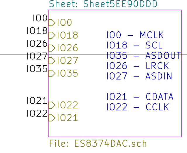
ES8374 audio chip
For sound, I used ES8374 as a DAC and ADC. The microcircuit contains a built-in low frequency amplifier ~ 1.25 Watt. It is supported out of the box by Espressif Audio Development Framework . In the small QFN-28 package we get Mono DAC, ADC for microphone and ULF with SDK support. What is needed for such a device

Launched BT Speaker from the pipeline_bt_sink example
I took the lyrat_v4_3 board in the settings. Fixed codec on AUDIO_CODEC_ES8374_DEFAULT_HANDLE
Configured GPIO ports
esp_err_t get_i2s_pins(i2s_port_t port, i2s_pin_config_t *i2s_config)
{
    AUDIO_NULL_CHECK(TAG, i2s_config, return ESP_FAIL);
    if (port == I2S_NUM_0 || port == I2S_NUM_1) {
        i2s_config->bck_io_num = GPIO_NUM_18;
        i2s_config->ws_io_num = GPIO_NUM_26;
        i2s_config->data_out_num = GPIO_NUM_27;
        i2s_config->data_in_num = GPIO_NUM_35;
    } else {
        memset(i2s_config, -1, sizeof(i2s_pin_config_t));
        ESP_LOGE(TAG, "i2s port %d is not supported", port);
        return ESP_FAIL;
    }
    return ESP_OK;
}
And threw out the initialization of audio_board_key_init and audio_board_led_init. By the correct one you need to determine your custom board
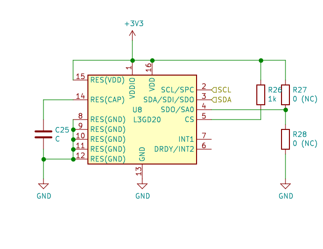
Gyroscope L3GD20
I decided to add the gyroscope L3GD20. An interesting feature is that it can be connected as an SPI or I2C device. R27, R28 in case of connection via I2C set the address
// L3GD20H addressesOn GitHub there is a library l3gd20h-esp-idf
#define L3GD20H_I2C_ADDRESS_1 0x6a // SDO pin is low
#define L3GD20H_I2C_ADDRESS_2 0x6b // SDO pin is high
Thus, we have 3 devices on I2C. ADC-DAC ES8374 control, buttons on MCP23017 and L3GD20 itself. Launched all three
i2cdetect
i2c-tools> i2cdetect
0 1 2 3 4 5 6 7 8 9 a b c d e f
00: — -- — -- — -- — -- — -- — -- — -- — --
10: 10 — -- — -- — -- — -- — -- — -- — -- —
20: — -- — -- 24 — -- — -- — -- — -- — -- —
30: — -- — -- — -- — -- — -- — -- — -- — --
40: — -- — -- — -- — -- — -- — -- — -- — --
50: — -- — -- — -- — -- — -- — -- — -- — --
60: — -- — -- — -- — -- — -- 6a — -- — -- —
70: — -- — -- — -- — -- — -- — -- — -- — --
But for some reason L3GD20 does not give coordinates. WHO_AM_I correctly answers 0xd4. the angles do not change. I do not have a capacitor C1 - 10nF, I tried to put it, which found the closest 100nF. I thought even though he was lying, but it seems that the internal converter does not start. And this is important
i2cdump
i2c-tools> i2cdump -c 0x6a
0 1 2 3 4 5 6 7 8 9 a b c d e f 0123456789abcdef
00: b6 5e 81 fc 05 50 31 83 c4 f9 85 d0 48 c6 00 d4 ?^???P1?????H?.?
10: 1a 15 16 ea c0 b9 4f 72 07 d8 a1 21 a1 00 14 02 ??????Or???!?.??
20: 07 00 00 80 00 00 0c 00 1a 00 13 00 16 00 00 20 ?..?..?.?.?.?..
30: 00 00 00 00 00 00 00 00 00 05 00 00 00 00 00 00 .........?..
40: 00 00 00 00 00 00 00 00 00 00 00 00 00 00 00 00…
50: 00 00 00 00 00 00 00 00 00 00 00 00 00 00 00 00…
60: 00 00 00 00 00 00 00 00 00 00 00 00 00 00 00 00…
70: 00 00 00 00 00 00 00 00 00 00 00 00 00 00 00 00…
Display 18 pin ILI9341

Calculated the backlight current as follows. Requires 90mA. Since the open-transistor drop is ~ 0.7V, the power supply for the backlight LEDs is 3.3V - 0.7V = 2.6V. And according to Ohm's Law 2.6V / 0.090A = 28.8 Ohm. Delivered 47 Ohm. It turned out a little dark. It will be necessary to reduce the resistance.
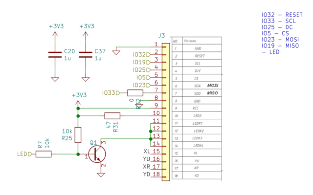
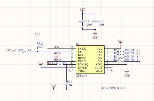
Also, the Touch XPT2046TS was separated. SPI pins hung in parallel with the display. XPT_CS is displayed on a separate pin. There is a doubt that it will work. If the display hadn't started up, I would have done experiments. For the console, it is not particularly needed. Took from example
Demos
Launched LVGL demo. In the example settings, I tried to set 40MHz for the SPI bus. The example worked a little faster than the video
But Doom started up and worked stably only at 32MHz. Although 26MHz for ILI9341 is already considered overclocking
spi_device_interface_config_t devcfg={
        .clock_speed_hz=26000000,               //Clock out at 26 MHz. Yes, that's heavily overclocked.
        .mode=0,                                //SPI mode 0
        .spics_io_num=PIN_NUM_CS,               //CS pin
        .queue_size=NO_SIM_TRANS,               //We want to be able to queue this many transfers
        .pre_cb=ili_spi_pre_transfer_callback,  //Specify pre-transfer callback to handle D/C line
    };
Conclusion
ESP32 I / O ports are not always enough to stuff to the maximum. In this regard, STM32 looks more attractive. But it does not have built-in Wi-Fi support.
In conclusion, I note that the device can run the Nintendo emulator ESP32-NESEMU, and the Nintendo Entertainment System emulator for the ESP32.
I ordered Game Console with Ali. It will be interesting to see what's inside. Possibly ESP32 too

I look forward to discussion and advice in the comments.