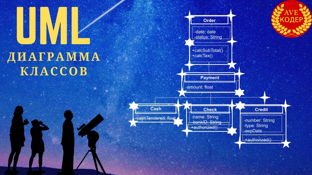
Ave, Coder! A UML class diagram illustrates the structure of a system, describing classes, their attributes, methods, and relationships between objects.
Even the smallest children know that UML comes from the Unified Modeling Language, if in Russian, it is a unified modeling language, which, as the legend says, was developed when serious uncles and aunts finally got tired of swimming in a variety of circles, dashes and clouds.
For those who are too lazy to read:
The main character
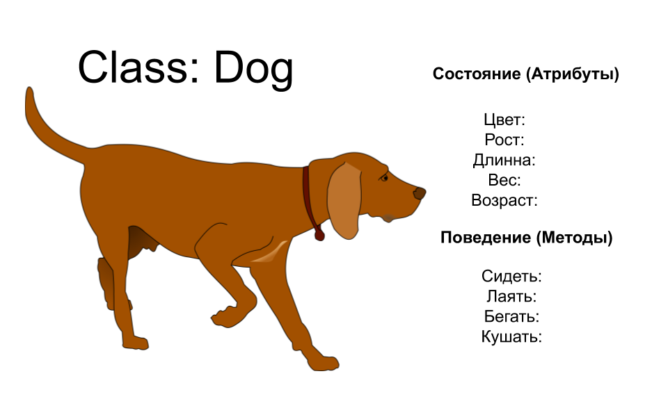
First, let's remind ourselves what a class is? In a nutshell, a class is a template for creating objects that provides initial state values: initialization of variable fields and implementation of the behavior of fields and methods.
Essentially, a class describes what an object can be.
A class represents a concept that describes state (attributes) and behavior (methods). Each attribute has its own type, each method has its own signature, but in the class diagram only the class name is required information to be filled in, which is logical - even the best psychics in the world will not be able to understand what this unnamed square is and what it generally refers to.
The class name is written in the uppermost division, followed by the class attributes, the types of which are written after the colon, and finally, in the lower division, there are methods.
The type that a method can return is written after the colon at the very end of the method signature. Scope modifiers are shown in front of class attributes and methods.
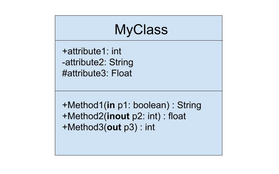
Each parameter in a method can also have a description of the direction of the method: in, out, inout.
In this illustration, method1 uses p1 as an input and the value of p1 is somehow used by the method, and the method does not change p1.
Method2 takes p2 as an I / O parameter, the p2 value is somehow used by the method and takes the output of the method, but the method itself can also change p2.
Method3 uses p3 as an output parameter, in other words, the parameter serves as a repository for the method's output value.
Perspectives on class diagrams in the software development lifecycle
We can use class diagrams at different stages of the software development lifecycle and typically gradually model class diagrams from three different perspectives as we progress through the levels of detail.
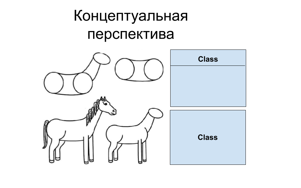
Conceptual perspective is when diagrams are interpreted as describing things in the real world. Thus, if we take a conceptual perspective, we draw a diagram that represents the concepts in the study area. These concepts are related to the classes that implement them. The conceptual perspective is considered language independent.
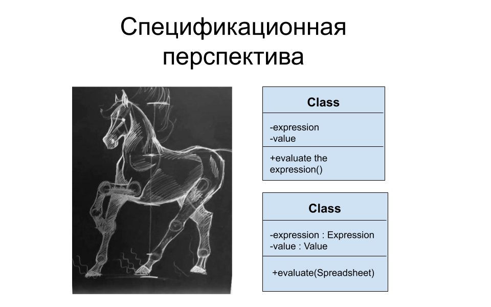
A specification perspective is when diagrams are interpreted as describing abstractions of software or components with specifications and interfaces, but not tied to a specific implementation.

An implementation perspective is when diagrams are interpreted as describing software implementations in a particular technology and language.
Thus, if you take an implementation perspective, you are looking at software implementation.
Relationship types
Next, I will present six main types of class relationship notation that are most common in UML diagrams.
Association.

Like links connecting objects, associations link classes. In order for objects to be connected, there must be an association between them.
If we assume that we have two classes that interact with each other, a continuous connecting line should be drawn between them, indicating the association on the diagram. Often we can also see a verb that conveys its meaning.
In addition, we can also specify the multiplicity, that is, the number of objects that can take part in the relationship. The multiplicity is specified as a comma-separated list of intervals, in which each interval is represented as a minimum-maximum.
For example, one student can learn from many teachers.
But a teacher can teach many students.
Inheritance
Or sometimes it is also called - generalization.
As the name suggests, this is a schematic representation of the relationship between a parent class and its descendants. The hollow arrow always points towards the parent class.
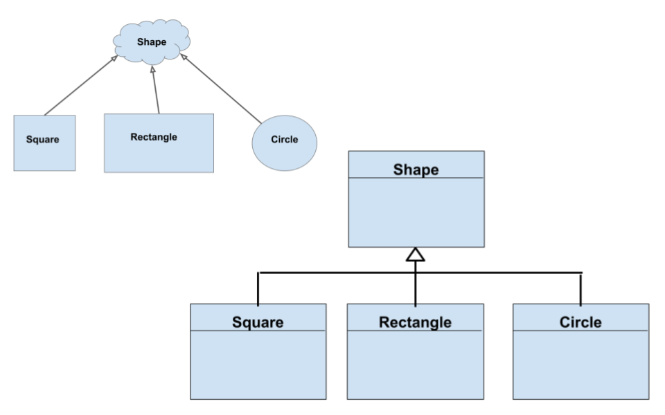
A classic example of inheritance: the square, rectangle, and circle classes, which inherit from the parent figure class.
We have the right to depict inheritance both separately for each class, and to combine them.
If inheritance comes from an abstract class, then the name of such a parent class is written in italics.
Implementation
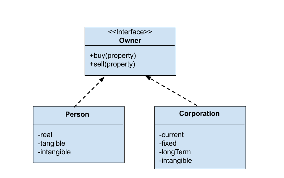
Usually, this means the relationship between an interface and objects that implement this interface.
For example, the Owner interface has methods for buying and selling private property, and the relationship of the Person and Corporation classes that implement this interface will be denoted in the diagram as a dashed line with an arrow pointing towards the interface.
Dependency An
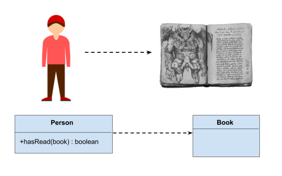
object of one class can use an object of another class in its method.
If the object is not stored in the class field, then this kind of interclass relationship is modeled as a dependency.
Dependency is, in fact, a special case of association of two classes, in this case, changes in one class will inexorably entail changes in the other.
For example, the Person class has a hasRead method with the book input parameter, which returns true if, for example, the person has read a book.
A dependency is indicated by a dashed line with an arrow pointing to the class on which, for example, methods of another class depend.
Aggregation
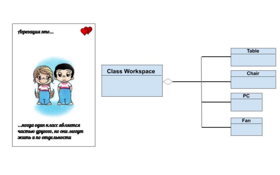
A special type of relationship between classes where one class is part of another.
For example, a programmer's workplace consists of a chair, a table, a computer and a fan, but if the class "workplace" is deleted, we will simply have all these classes, only separately.
Aggregation is shown as a continuous line with a hollow diamond directed from classes that are part of a class to the aggregator class.
Composition
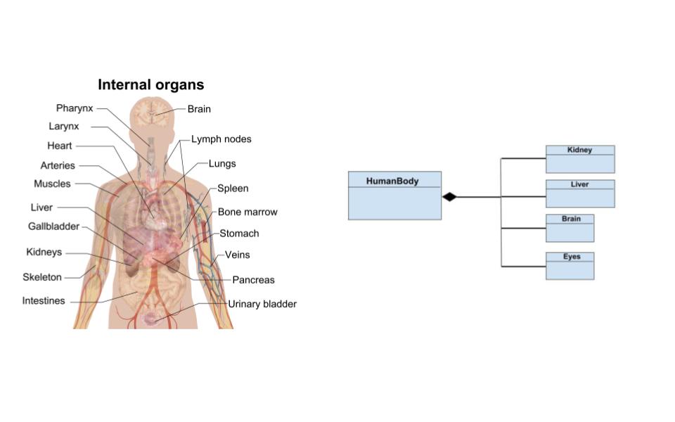
In fact, a kind of aggregation, only in this case, classes that are part of another class are destroyed when the aggregator class is destroyed.
For example, our body is made up of organs, but by themselves they are not viable.
The composition is indicated in a way similar to aggregation, but this time the diamond is completely filled.
Finalchka
The UML can be very useful for beginners who are at the stage of understanding “what should go where and from what inherited”. As our English-speaking colleagues say: “it helps to see what the whole forest looks like behind the tree trunks”.
Therefore, before starting your, albeit small, but stunning project, do not grab the code right away. First, design your application architecture in UML.
Ave!