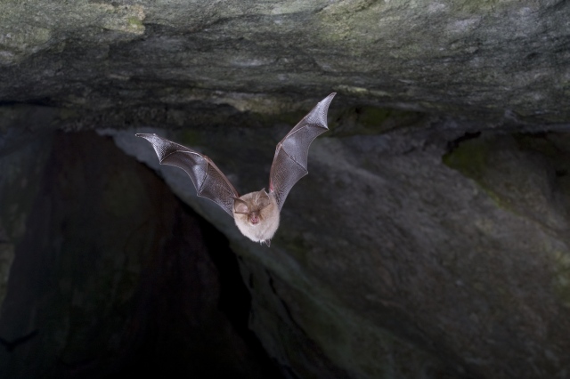
Lesser horseshoe bat
This project describes the creation of the so-called. bat detector - a device that allows you to hear and record the sounds made by bats. You are probably aware that bats emit ultrasound for echolocation. The frequency of these sounds is out of the range perceivable by the human ear, so they cannot be heard directly. The bat detector uses a special microphone capable of picking up these high-frequency sounds and converting them into sound that falls within the audible range.
There are three types of bat detectors . For myself I made a heterodynedetector. Its disadvantage is that it makes it more difficult to distinguish different types of bats when compared to recording high frequency sounds. I'll explain later how a heterodyne detector works, but first let's look at the microphone needed to record ultrasound.
When choosing a microphone, at first I considered two options:
- an electret microphone - everything that I found, according to the documents, works only in the range from 10 to 20 kHz, but if you believe some resources, then some of their types also perceive ultrasound to some extent. However, since their official descriptions do not indicate this, it would take a lot of trial and error to go through the various brands and try them out. So I gave up on this type of microphone.
- piezoelectric sensors... They are, for example, found in the popular HC-SR04 ultrasonic rangefinders, which are ubiquitous and cheap. Their downside is that their sensitivity is very close to the resonant frequency, somewhere around 40 kHz. And when moving away from this frequency, the sensitivity drops sharply. So they don't fit either.
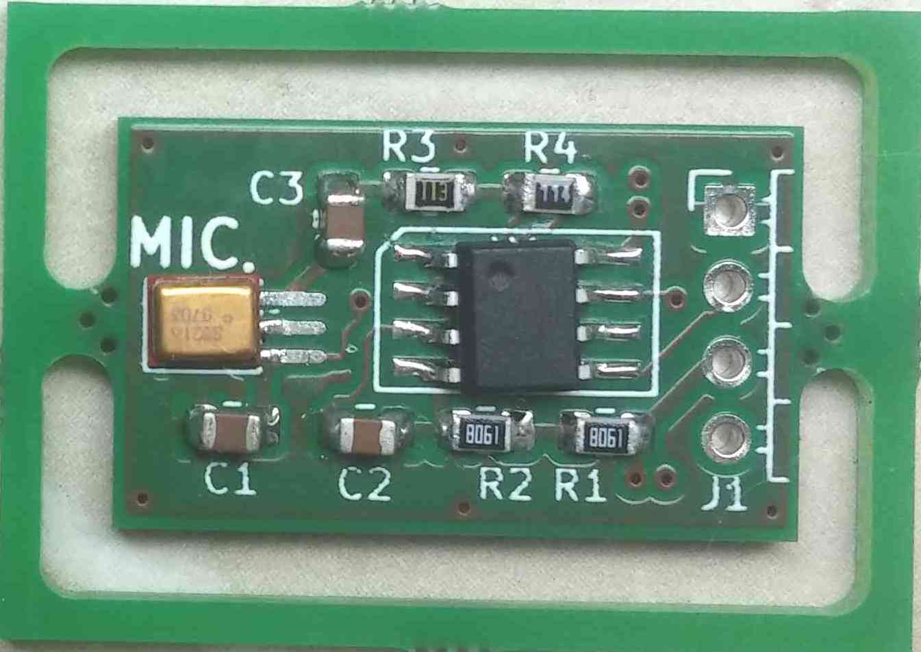
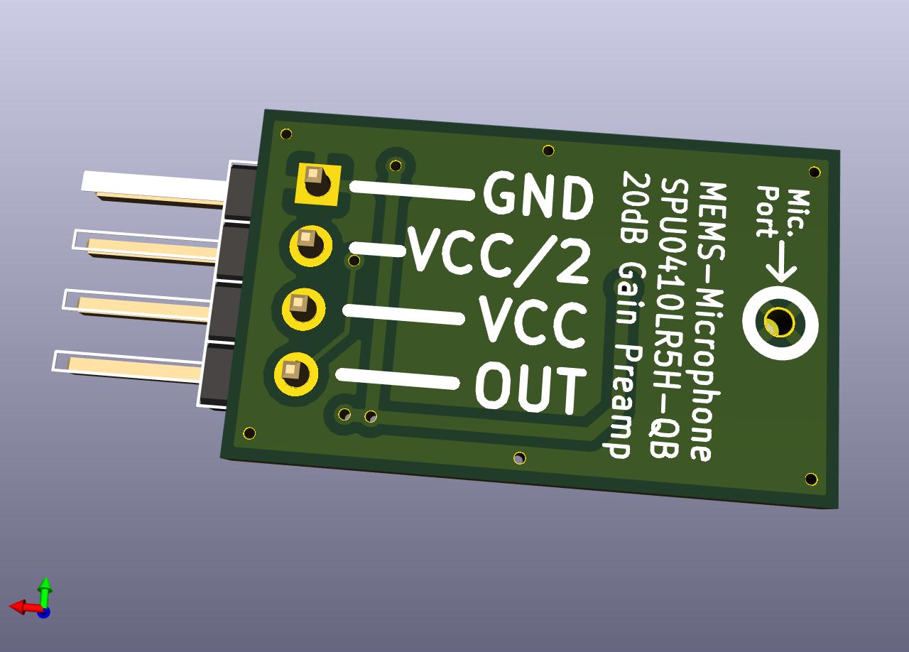
Instead, I ended up finding a Knowles SPU0410LR5H microphone, a MEMS type microphone... According to the specification, this microphone has a fairly flat response curve at all frequencies up to 80 kHz, so it is very well suited for this project. In addition, it has an internal high S / N preamplifier. The main disadvantage of this microphone is that its housing is not intended for homemade projects. It's tiny (3.76 x 3 mm!), And its contacts are inside the case. I searched the Internet, and came across the page of the user hackaday.io Alan Green, who also used this microphone in his project. He came up with a good idea to make a special board for this microphone, so that it can be soldered by hand. The point is to lengthen the pads so that they stick out of the component. I took this idea and designed a small board for a microphone and a dual op amp. The latter provides virtual ground (at half the supply voltage), as well as a 20 dB amplifier stage (i.e., 10 times). At first I was skeptical about soldering this microphone by hand, but everything worked well - all 6 boards that I soldered succeeded. I recorded a video of the soldering for clarification. The design of the boards is also made public .

Let's start explaining the principle of operation of a heterodyne bat detector. Let's start by looking at the signals emitted by mice. They can be modeled as a signal amplitude-modulated ultrasonic carrier frequency and envelope signal like a short "chirp" is the signal (a signal with linear frequency modulation ).
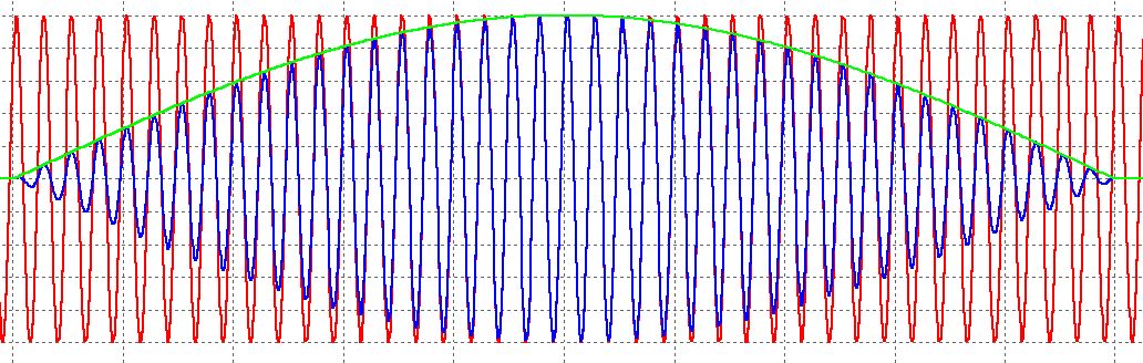
In the ultrasound diagram, the carrier is shown in red, the envelope of the chirp is shown in green, and the total sum is shown in blue. To translate the signal into the human-audible range, you need to convert it so as to preserve the envelope (chirp), modulating it with a carrier signal with a lower frequency (for example, in the range of 1-5 kHz). How can this be achieved?
To understand how this is done from a mathematical point of view, we useknown trigonometric identities :
2sin (x) ⋅sin (y) = cos (x − y) −cos (x + y)
2cos (x) ⋅cos (y) = cos (x − y) + cos (x + y)
2sin (x) ⋅cos (y) = sin (x − y) + sin (x + y)
2cos (x) ⋅sin (y) = - sin (x − y) + sin (x + y)
If we take our signal model of bats, it can be modeled as follows:
carrier (t) = sin (2πf c t)
chirp (t) = sin (2πf chirp t)
bat (t) = carrier (t) ⋅chirp (t)
where is the ultrasonic frequency carrier - f c , and the frequency of the chirp signal - f chirp . For this example, let's assume:
f c = 40 kHz
f chirp = 1 kHz
Using trigonometric identities, we get:
bat (t) = sin (2πf c t) ⋅sin (2πf chirp t) = 1/2 cos (2π (f c −f chirp ) t) - 1/2 cos (2π (f c + f chirp ) t)
The modulated signal consists of two frequencies symmetrically located around the carrier frequency, in this example
40 kHz - 1 kHz = 39 kHz
40 kHz + 1 kHz = 41 kHz
This is the lower LSB and upper USB sideband :
f LSB = f c −f chirp
f USB = f c + f chirp
We can now use the same principle to convert the mouse signal to a lower, audible frequency. To do this, you need to multiply the signal by the frequency of the local LO generator - this is the difference between the carrier frequency of the signal and the desired carrier frequency (in our case, the audible frequency at which we would like to hear the cries of bats). This technique is called heterodyning.In our example, let's say that we want to hear the screams of mice at a frequency of 5 kHz, which is clearly audible to humans. Then:
f target = 5 kHz
f LO = f c −f target = 35 kHz
LO (t) = sin (2πf LO t)
Putting it all together, we can rewrite the terms of the equations using trigonometric identities:
bat (t) ⋅LO (t) = (1/2 cos (2πf LSB t) −1/2 cos (2πf USB t)) ⋅sin (2πfLOt)
= 1 / 2cos (2πf LSB t) ⋅sin (2πf LO t) - 1 / 2cos (2πf USB t) ⋅sin (2πf LO t)
= 1/4 (sin (2π (f LO −f LSB ) t) + sin (2π (f LO + f LSB ) t) - sin (2π (f LO −f USB ) t) - sin (2π (f LO + f USB ) t))
(considering that sin (−x) = - sin (x)),
= 1/2 (−1 / 2sin (2π (f LSB −f LO) t) + 1 / 2sin (2π (f USB −f LO ) t) + 1 / 2sin (2π (f LSB + f LO ) t) - 1 / 2sin (2π (f USB + f LO ) t))
= 1/2 (−1 / 2sin (2π (fc − f LO -f chirp ) t) + 1 / 2sin (2π (fc − f LO + f chirp ) t) + 1 / 2sin (2π (fc + f LO - f chirp ) t) - 1 / 2sin (2π (fc + f LO + f chirp ) t))
= 1 / 2cos (2πf target t) ⋅sin (2πf chirp t) + 1 / 2cos (2πf 2 t) ⋅sin (2πf chirp t)
It can be seen that the first term, cos (2πf target t) ⋅sin (2πfchirp t) is exactly what we want, a chirp envelope modulated with an audible frequency of 5 kHz. The second term is again a chirp signal modulated at a higher frequency, f 2 = f c + f LO , in this case 75 kHz. The second component is far out of the audible range and is easily cut off by the high-pass filter in the bat detector circuit.
Now that we have a theoretical understanding of how the heterodyning principle can be used to build a bat detector, how do we put it into practice? The main thing is to multiply the input signal by the LO signal, which in practical electronics is not so easy to do. There are circuits for analog multiplication (for example, the Gilbert cell), and we can use a suitable IC (such as NE612 ) in conjunction with a sine wave generator (for example, a Wien bridge generator ). However, such a solution will be difficult, and ICs for analog multiplication such as NE612 or similar are rare and expensive.
It turns out that there is a simpler option, and it can be assembled from common standard components. We can assemble a frequency mixer with analog switching. While this is not an ideal mixer, since it does not actually multiply both signals, we will soon see that it still works well enough.
For now, let's look at the diagrams and try to figure out how this works.
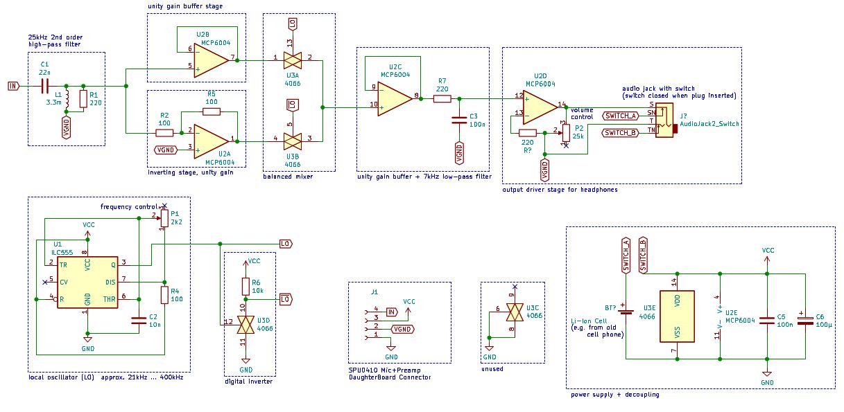
On the left in the diagram, the microphone output is fed to a high-pass LC filter of the second order, which removes audible frequencies below 20 kHz, and allows only ultrasound to pass through (since this is what we need). Resistor R1, parallel to the inductor, is required - it dampens the resonance.
After the high-pass filter, the signal comes to two stages of operational amplifiers, with coefficients 1 and -1 (i.e., it inverts the signal). We now have both the mouse signal and its inverted counterpart.
At the bottom left in the diagram, you can recognize a bistable multivibrator with the famous IC 555... Potentiometer P1 can monitor the entire circuit and create a square wave with ~ 50% duty cycle and variable frequency from 20 kHz to 400 kHz. In our case, it will be the signal of the local oscillator LO, but unlike our mathematical model, this wave is square, not sinusoidal. The LO signal comes to the inverting stage, which consists of an analog switch U3D and a resistor R6. Here the analog switch is used as a digital inverter, and since the CD4066 IC has 4 analog switches, we have two spare ones, one of which can be used as an inverter, and save on components. It works simply: if the LO signal is low, the switch is open, and R6 pulls the output signal from the switch up. If the signal is high, the key is closed, and the output from the key is connected to ground. This is how an inverted signal is obtained....
Now let's look at the part of the circuit labeled “balanced mixer”. The non-inverted mouse signal is fed to an analog switch that controls the LO signal. The inverted signal is fed to another key, which controls the signal... Key outputs are connected. What does this part of the circuit do?
Let's consider the case where the LO signal is 0 (low) and therefore the signal1 (high). In this case, the lower key U3B is closed and the upper key U3A is open. Hence, an inverted mouse signal passes through. In the opposite case, when the LO signal is 1 (high), and therefore the signal0 (low)., The lower key U3B is open and the upper U3A is closed. Then the non-inverted signal passes. Recall that this switching occurs at a frequency f LO determined by the 555 timer loop.
Can this behavior be mathematically modeled? Essentially, this mixer circuit multiplies the signal by a square wave that switches between +1 and -1. This is equivalent to switching the output signal between inverted and non-inverted. Such a wave (let's call it r (t)) can be described by the so-called. with the sign (x) function :
Therefore, at the output of the mixer, we obtain the product bat (t) ⋅r (t). By itself, this does not explain anything yet - in order to understand how frequency mixing occurs, we need to apply a mathematical magic called the expansion of Fourier series. I will spare you the conclusion and give you the result immediately. In fact, using the Fourier series, one can show that:

So our square wave + 1 / -1 consists of an infinite set of sinusoids with a fundamental frequency f LO and its odd factors. What follows from this? If you ignore the constant 4 / π, you can see that r (t) is the sum of LO (t) and other additional higher frequencies LO 3 (t), LO 5 (t), and so on. From previous calculations, we have shown that:

Therefore, it can be calculated that:
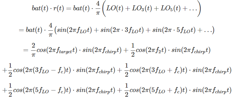
We see again that the first term 2 / π cos (2πf target t) ⋅sin (2π f chirp t) is what we want, however with our imperfect analog switchable mixer we end up with a bunch of other unnecessary terms. However, all of these unnecessary frequency components have much higher frequencies than our target f target . Therefore, we can use a high-pass filter to eliminate these components, and obtain a final signal approximately equal to 2 / π cos (2π f target t) ⋅sin (2π f chirp t).
If we return to the circuit, then the output from the mixer comes to the buffer stage, and then to the low-pass RC filter with a coupling frequency of ~ 7 kHz. The last amplification stage provides an adjustable gain and serves as an output driver (for example, headphones).
To better understand how frequency mixing works, I made a circuit simulator in LTSpice . You can download the simulation files and play with them.
A couple of notes on the components. I wanted the whole circuit to be powered by a single lithium-ion battery since I have a bunch of them from old phones and the like. Therefore, the whole circuit must operate with a power supply from 3 to 4 V. Therefore, the 555 timer and the 4066 analog switch must be selected in the form of CMOS - they already operate at 3 V. I used the CD4066B and ILC555. A quad op-amp must also operate at low voltage; I chose MCP6004 which I use a lot.
I didn’t lay the board, I soldered everything on the breadboard. If you want to make your own device with a board, download the diagram for KiCAD... I printed the case for the device and knobs for adjusting the volume and frequency on a 3D printer. The power turns on automatically when you insert the headphones into the jack. A flashing red LED indicates power on. The microphone board is located inside the case behind a small hole (pictured on the right).
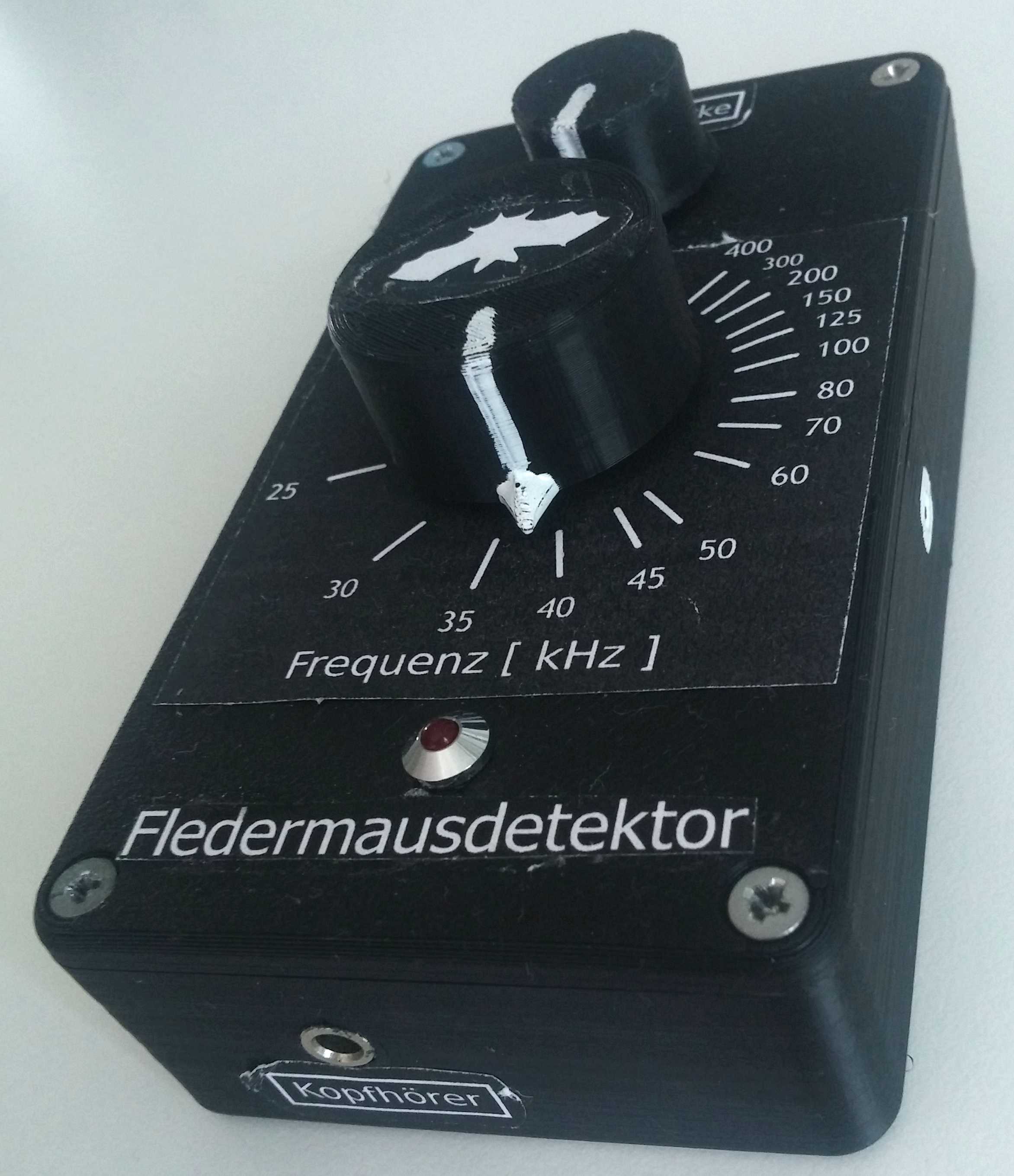
To calibrate the frequency scale, I checked the 555 output on an oscilloscope and marked the frequencies on the case. Then I drew the scale on the computer and printed it out.
And this is what we have all been waiting for. What does the cry of bats sound like on a detector? I offer you a recording of one fragment that I recorded around 10 pm when I saw the LM flying next to a lantern in the park. The frequency is adjusted to 40-45 kHz.
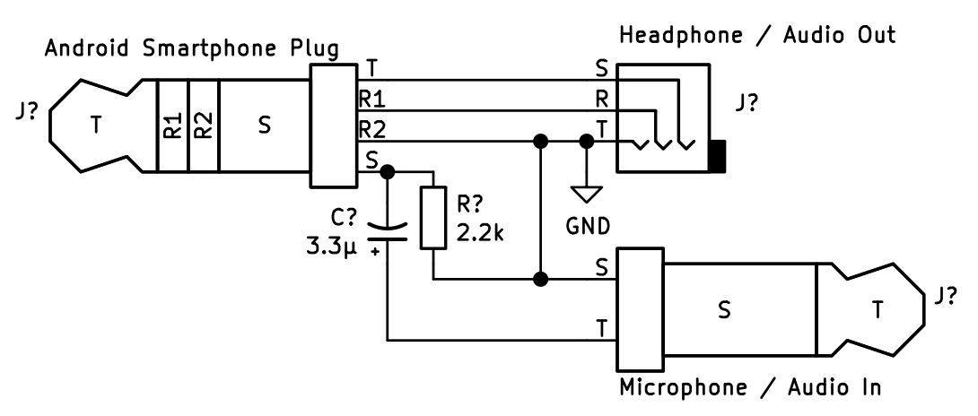
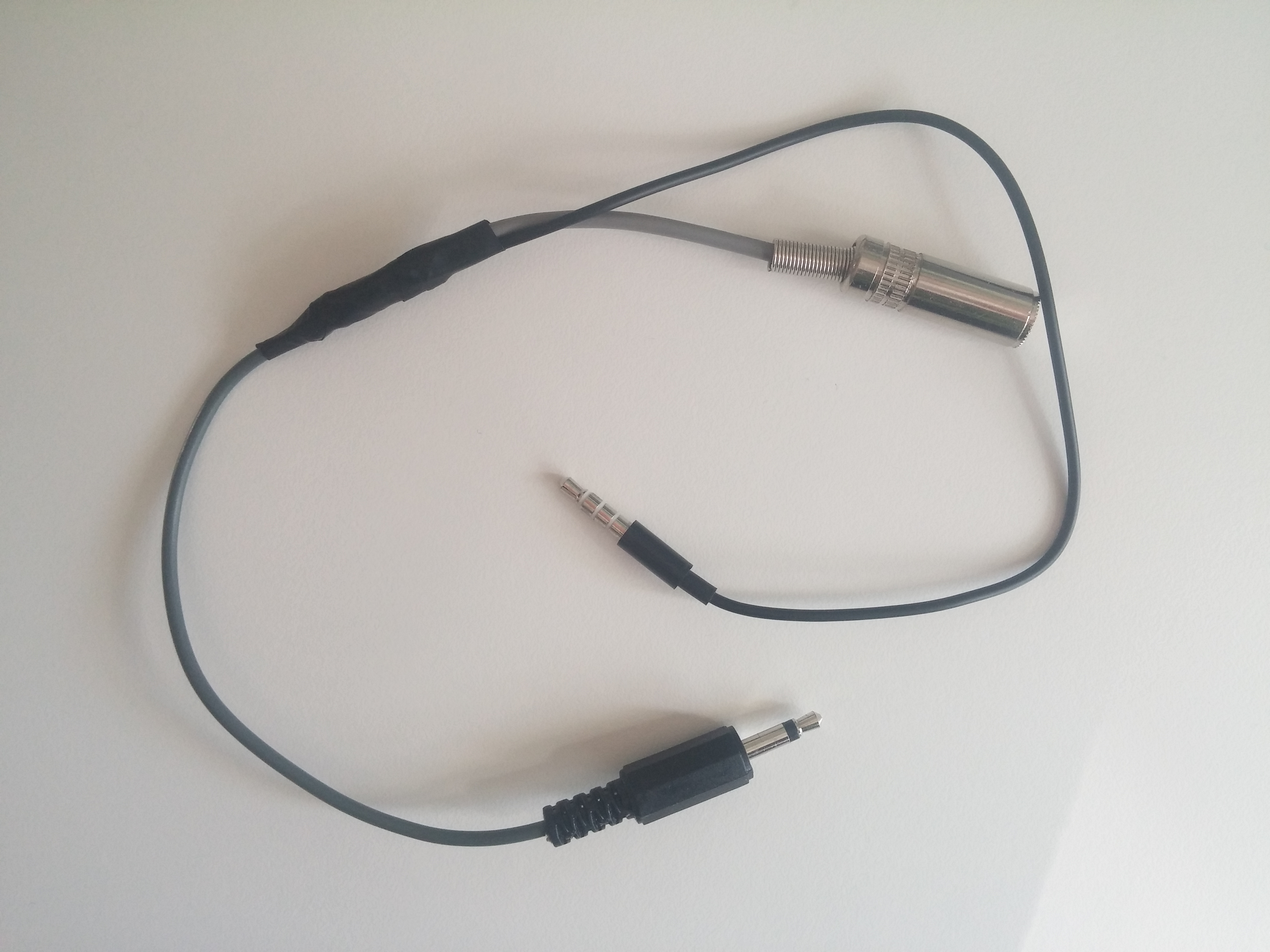
To record sound, I held my smartphone next to the detector's headphones, but it seemed very silly, so I decided to look for a better option. It turned out that most smartphones have a microphone input in the headphone jack - you just need to use a 3.5 mm pin with 4 contacts. Therefore, I developed an adapter that allows the detector to be connected to the microphone input of a smartphone, and headphones to the smartphone's headphone output. In order for the smartphone to recognize that a microphone is plugged into it, a 2.2 kΩ resistor is needed, and a 3.3 μF capacitor is needed to decouple the signal.
I also had to look for an application that can record and play audio at the same time so that I can listen to the recorded sounds in real time. I was happy with the RecForge II application , although there are probably others.
If you would like to assemble a heterodyne LM detector yourself and need a ready-made ultrasonic MEMS microphone on board, you can find it here:
- ELV shop
- MicBooster shop
There is no op-amp on these boards, so you will need to make one as well. The rest of the ingredients will be easy to find at your favorite store.
See also:
- " Sound transmission by amplitude modulation of ultrasound "
- " Module of underwater ultrasonic rangefinder "