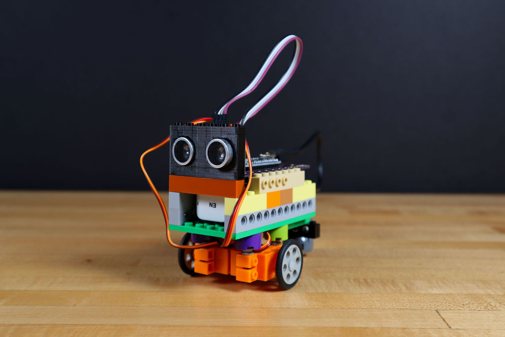
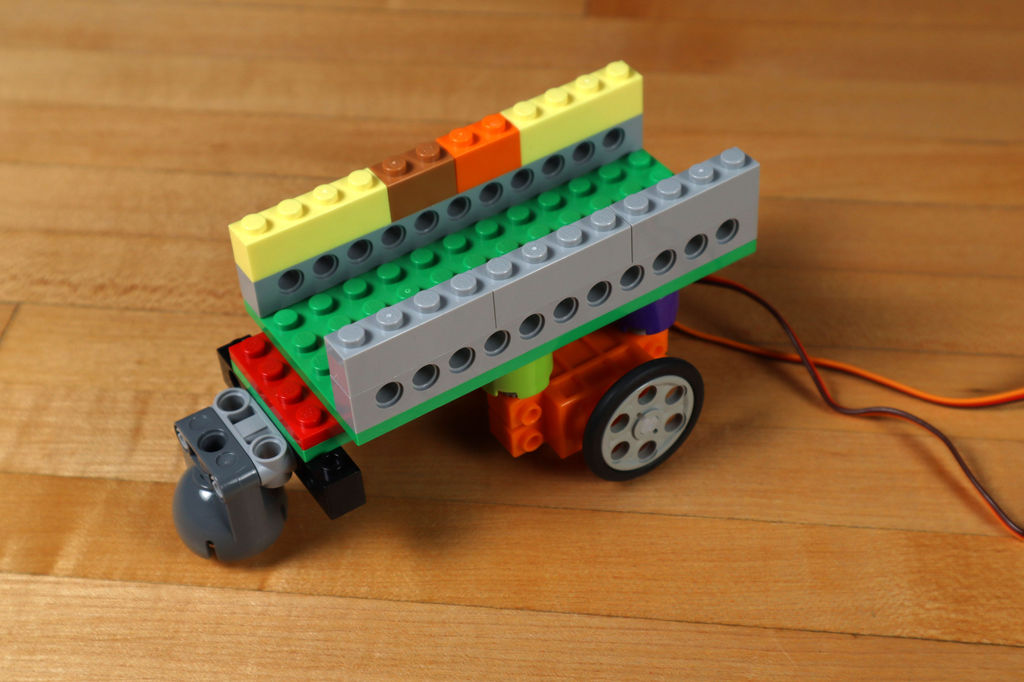
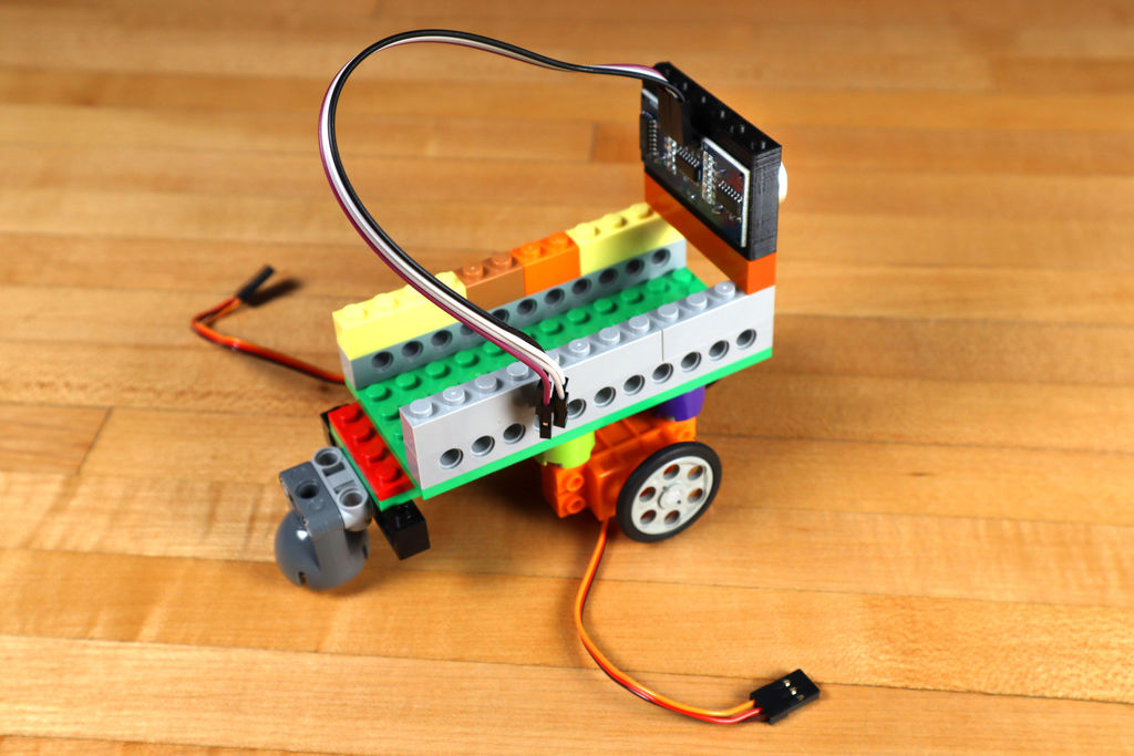
We love LEGO and Crazy Circuits [LEGO compatible electronics / approx. transl.], so we decided to combine them into a simple and interesting robot that can avoid obstacles. We will show you how to assemble such a robot and describe the process in detail. Your version of the robot may not be exactly the same as ours.
Here is a list of the required electronics and LEGO parts. Feel free to experiment with them.
Components
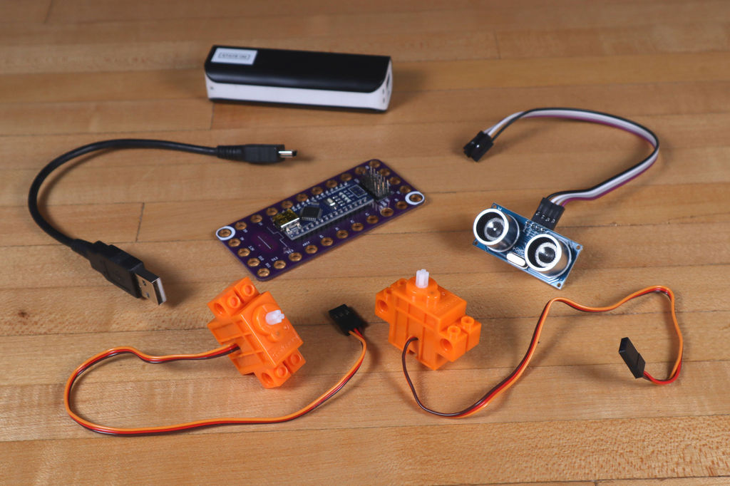
Electronics
- 1 x Robotics Board by Crazy Circuits
- 2 x LEGO Compatible Full Rotation Servo Motor
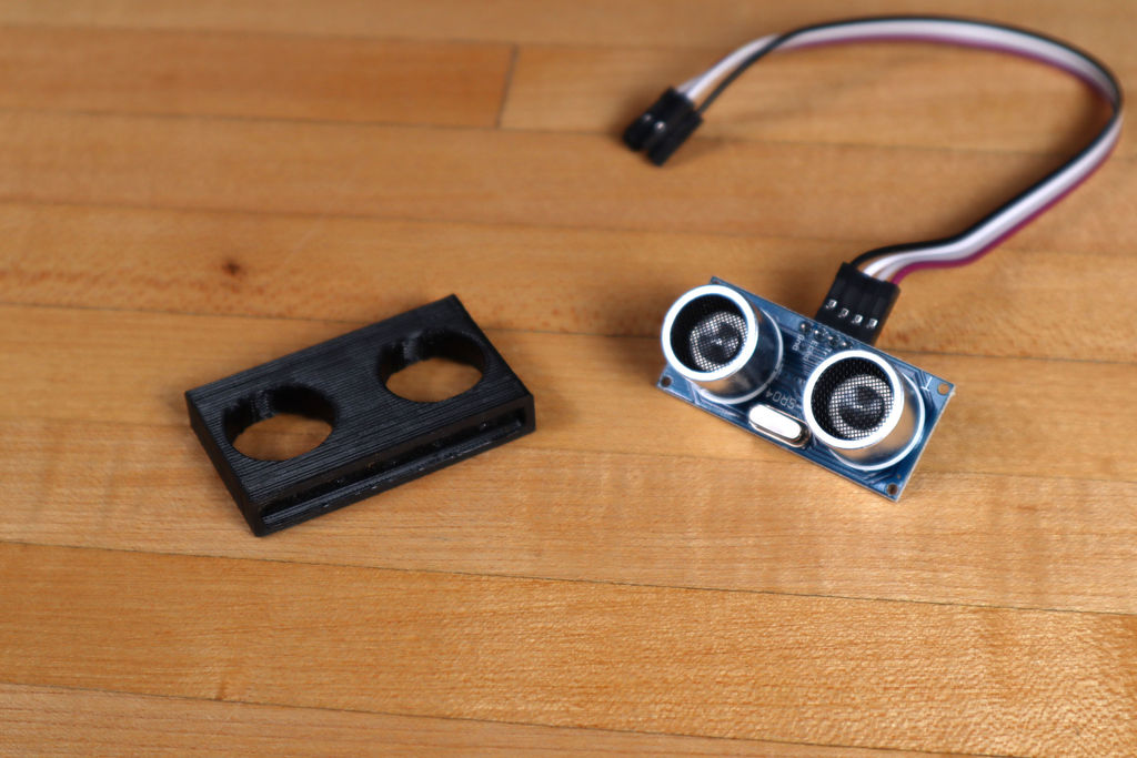
- 1 x Ultrasonic Distance Sensor HC-SR04
- 4 x female-to-female jumper cables
- 1 x external power supply with USB
For our project, we selected a small external power supply that fits snugly into our robot. You may have to design your own for your external power supply, or for a set of batteries.
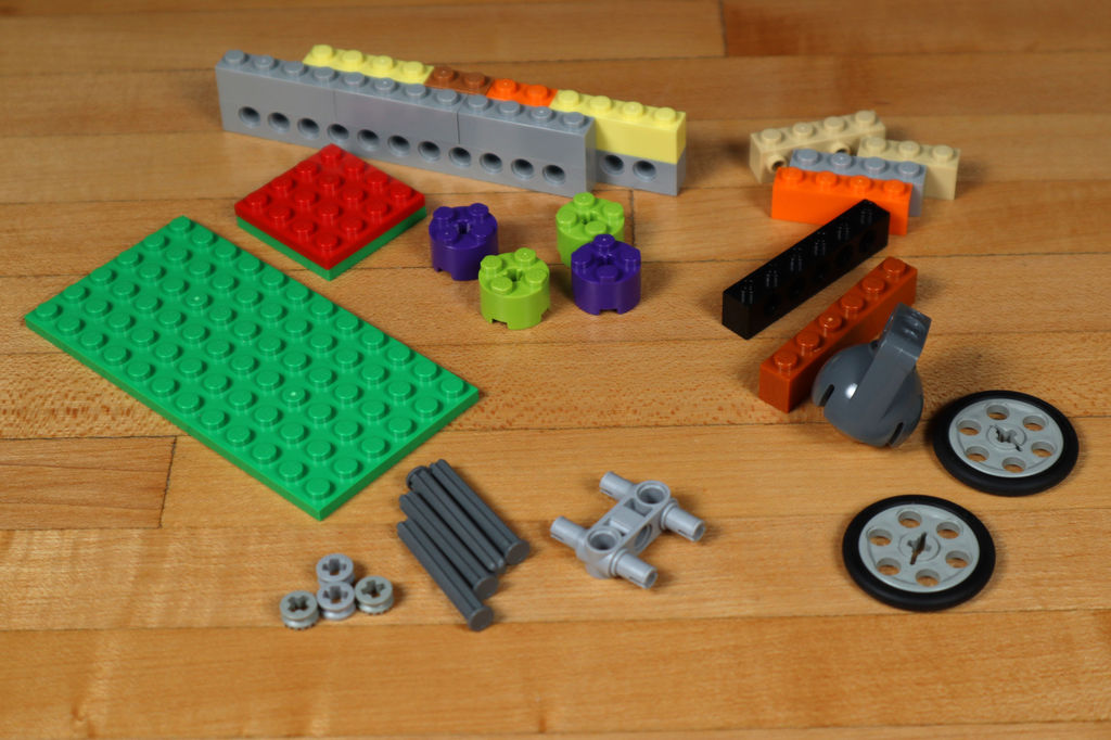
Lego
We used various details, but we recommend that you do it as you see fit, and from what you have on hand. It is important that you have a way to attach the servos to the bottom, the ultrasonic sensor so that it looks forward, and somehow secure the board and power supply. To do this, you can use double-sided tape, elastic bands, Velcro. There are links to our pieces in the BrickOwl store, however you can buy them wherever LEGO and compatible sets are sold.
- 2 x LEGO Wedge Belt Wheel (4185/49750)
- 1 x LEGO EV3 Technic Ball Pivots Set 5003245
- 1 x LEGO Technic Cross Block Beam 3 with Four Pins (48989/65489)
- 1 x LEGO Technic Brick 1 x 6 with Holes (3894)
- 2 x LEGO Axle 4 with End Stop (87083)
- 4 x LEGO Half Bushing (32123/42136)
- 4 x LEGO Brick 2 x 2 Round (3941/6143)
- 1 x LEGO Plate 6 x 12 (3028)
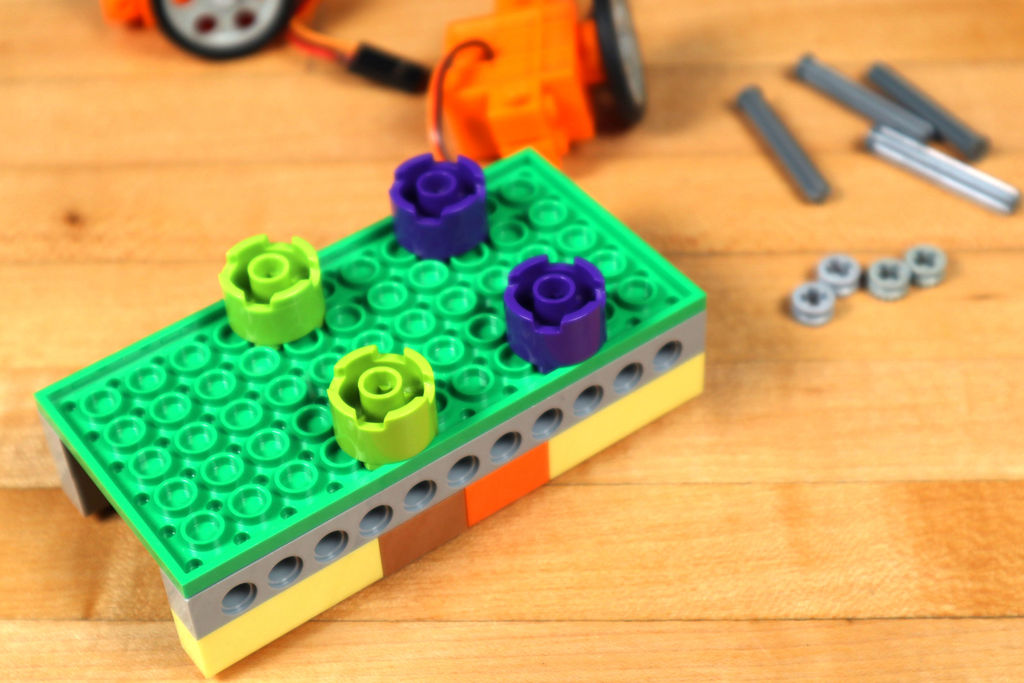
Step 1: build the LEGO chassis
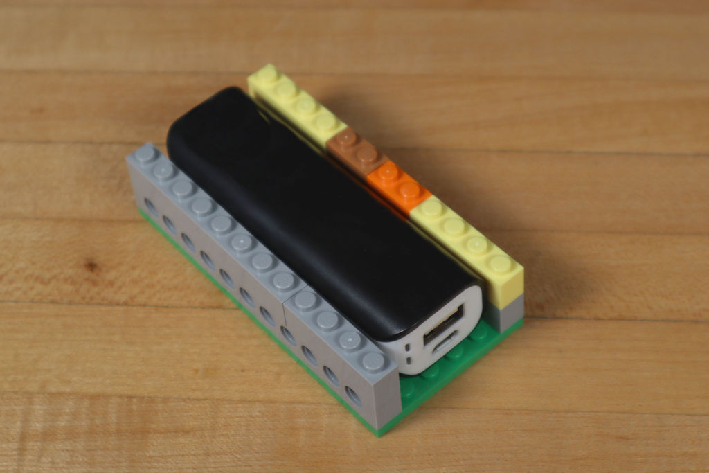
We started with a 6 × 12 LEGO plate, which was the minimum size we were happy with. You can use a larger one, but smaller will already be more difficult.
The width of the robot was dictated by the external power supply we had available, since we needed the ability to slide it into place. A larger battery will require a larger robot.
The chassis must be high enough to accommodate both the battery and the board on top.
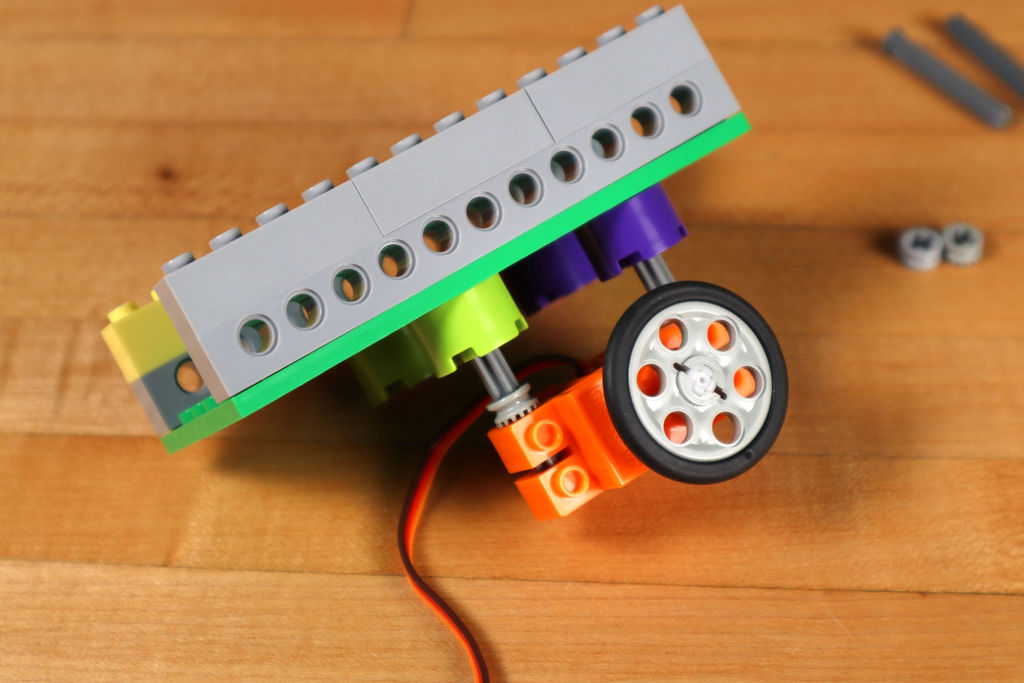
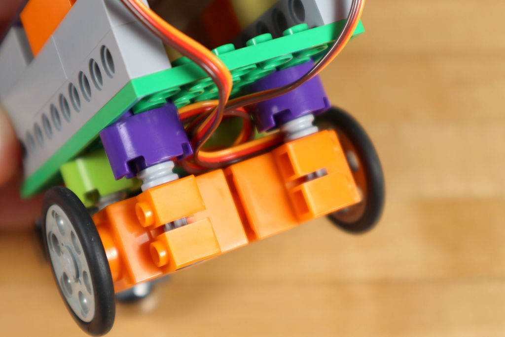
Step 2: add wheels
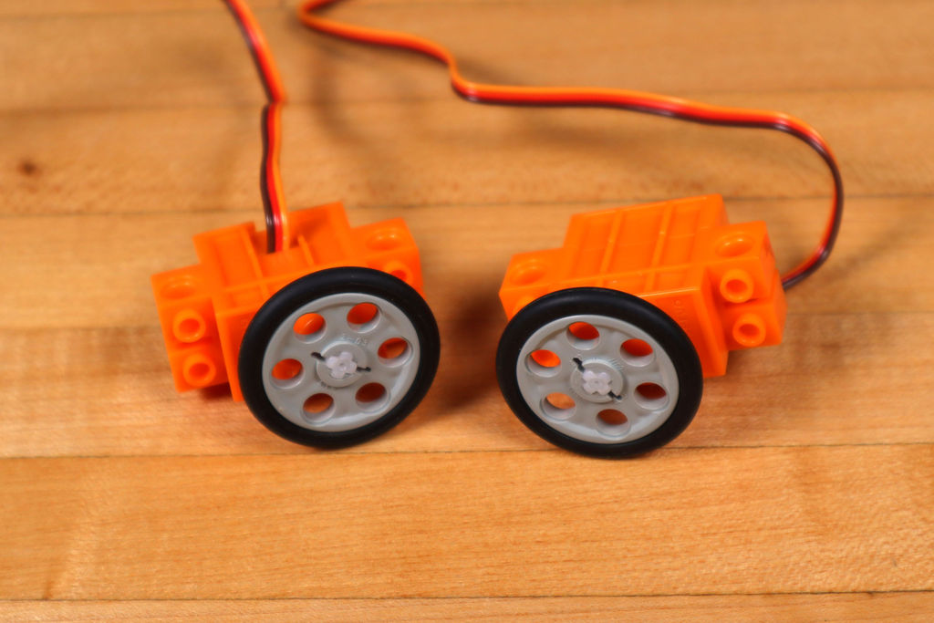
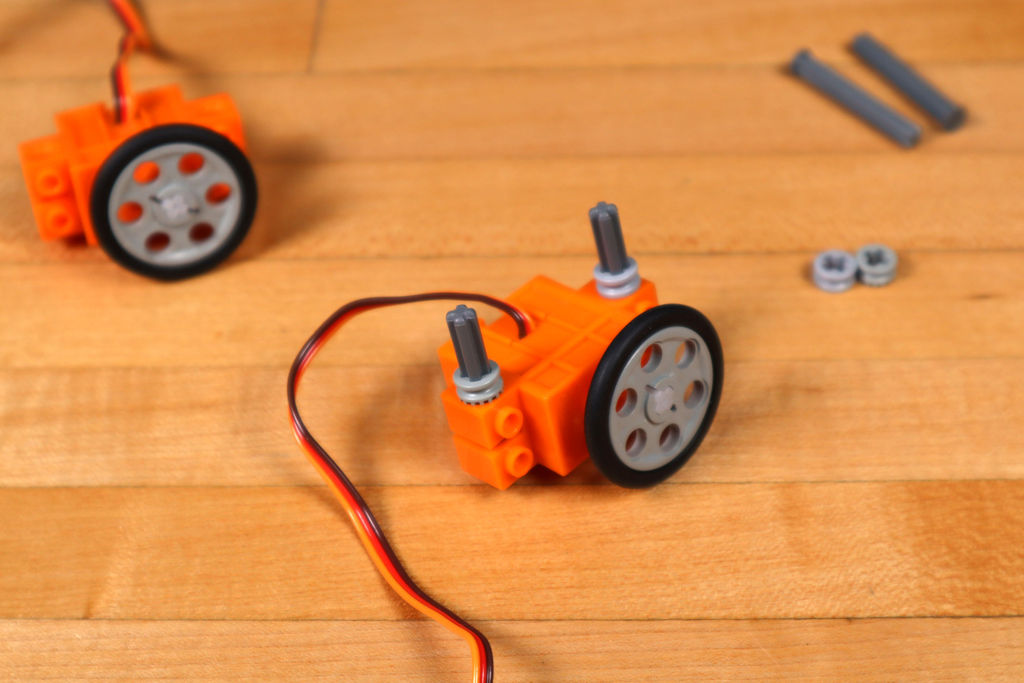
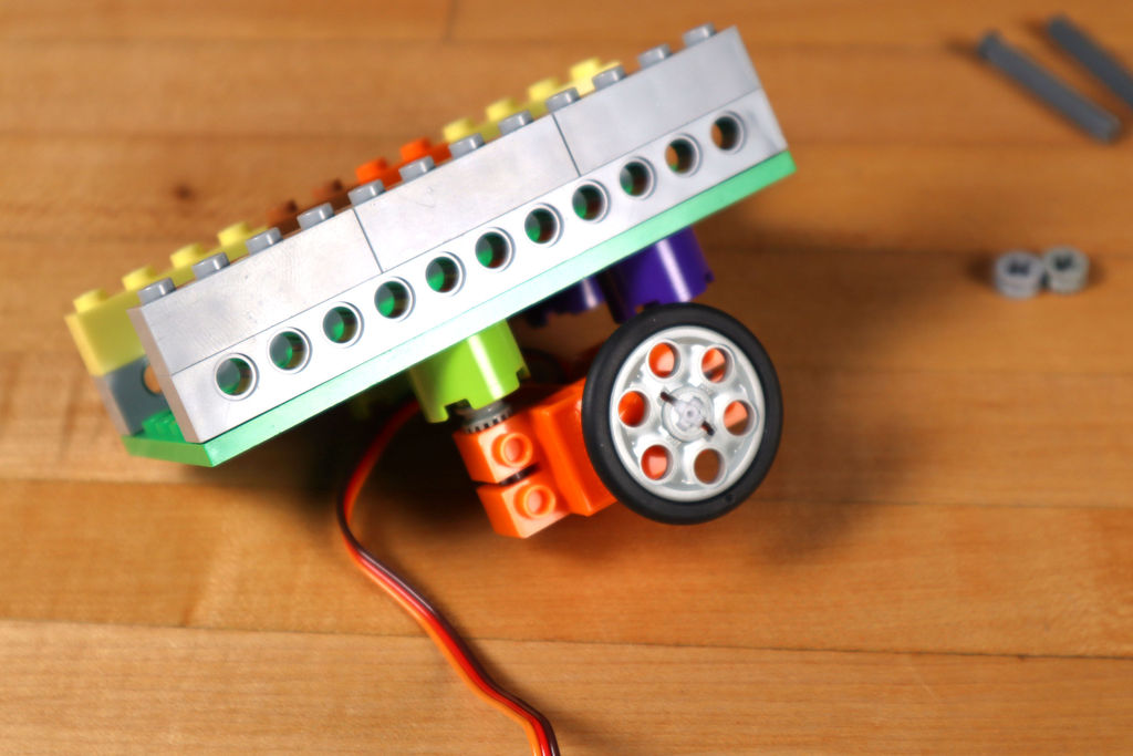
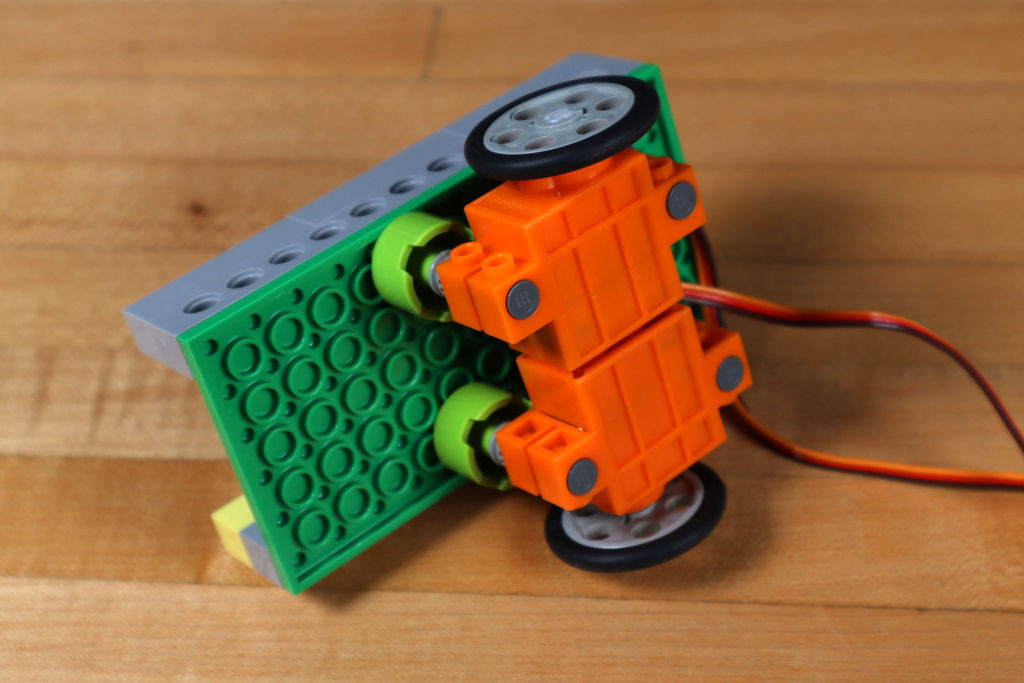

Each servo must be placed underneath the chassis. As a result, we needed the following components:
- Axle 4 LEGO with stopper (87083)
- LEGO hub (32123/42136)
- Round LEGO Brick 2 x 2 (3941/6143)
To fix two motors, you need 4 pieces of each of the components. After securing them, add a wheel: LEGO Wedge Belt Wheel (4185/49750).
As with other LEGO models, there are tons of options! We succeeded with the components that we listed, but you can try something else.
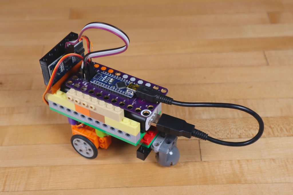
Step 3: add the video
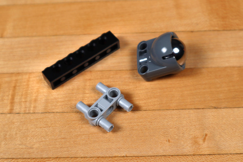
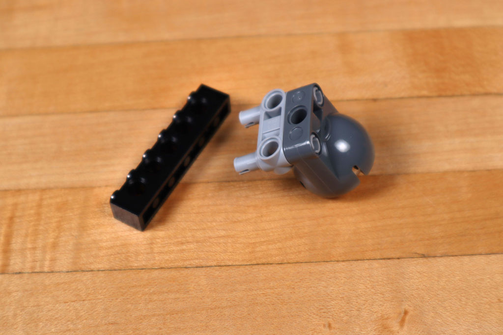
Our roller allows the robot to roll on a plane on two motorized wheels, acting as a third wheel - this makes it easier for the robot to turn and move.
To secure it, the following details were required:
- LEGO EV3 Technic Ball Pivots Set 5003245
- LEGO Technic Cross Block Beam 3 with Four Pins (48989/65489)
- LEGO Technic Brick 1 x 6 with Holes (3894)
In the previous version, we used just round LEGO pieces for the "leg" and it worked fine on smooth surfaces. But didn't work on carpet or not smooth floor. If you don't have a roller, consider using this "leg".
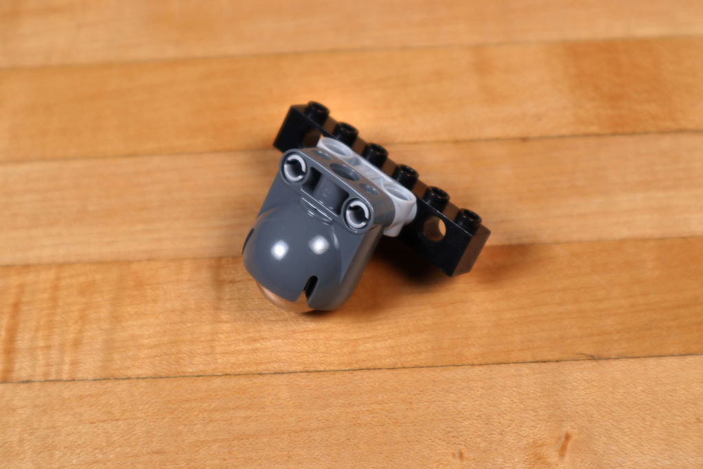
Step 4: add a distance sensor
The ultrasonic distance sensor must be attached to the front of the robot so that it “sees” where it is going and understands when to stop in order not to collide with an obstacle.
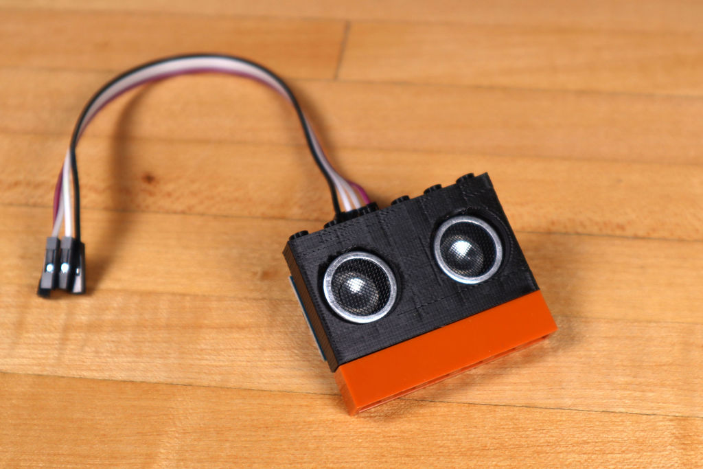
For the sensor, we 3D printed a LEGO-compatible housing. The model is posted on the Thingiverse website: www.thingiverse.com/thing : 3171004
If you don't have a 3D printer, figure out how to hold the sensor using LEGO pieces, duct tape, rubber bands, cable ties , etc. It is important that he looks straight ahead - where the robot is going when it moves forward.
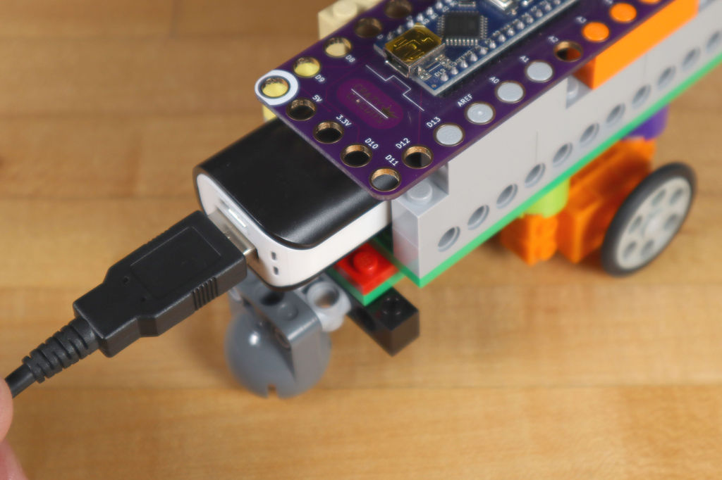
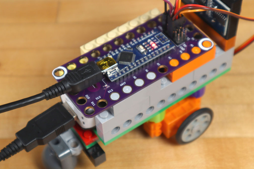
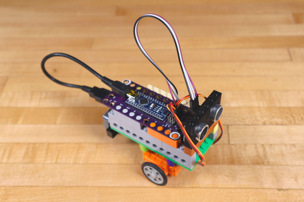
Step 5: add the board
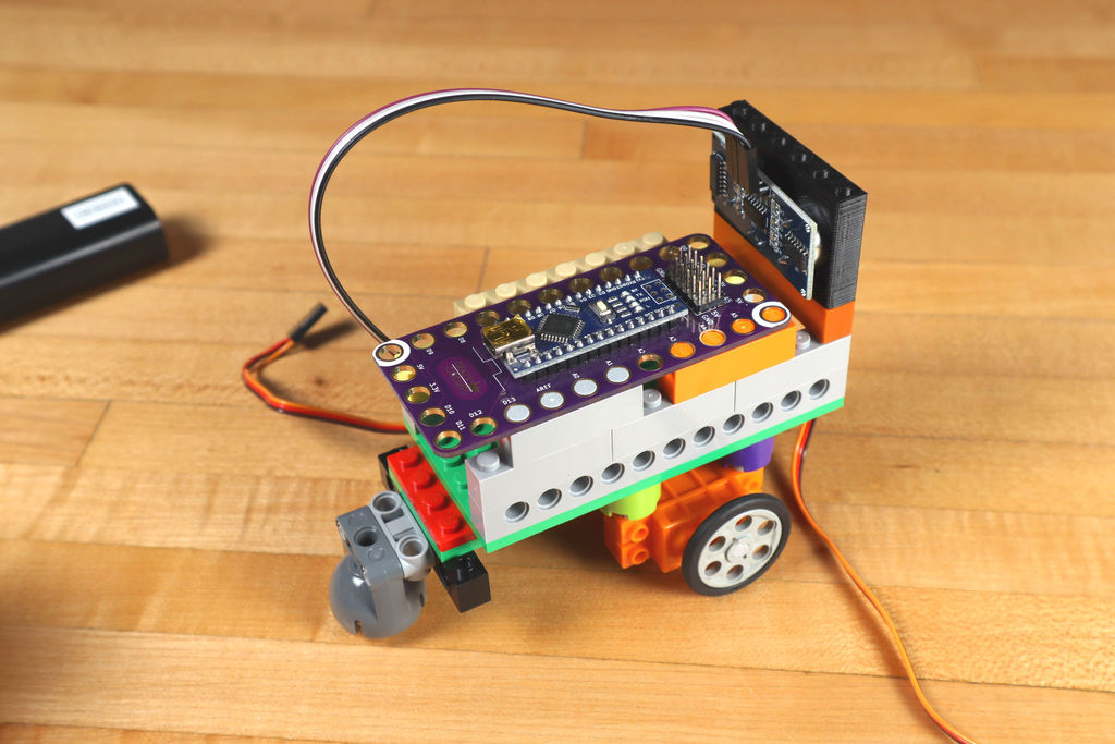
The fee is the brain of the entire operation. It sits on top of LEGO bricks, so it's easy to attach.
Typically, the Robotics Board is used in conjunction with a conductive tape that allows you to tinker electrical circuits directly on top of the LEGO, but since we only have two motors and a distance sensor, they can be connected directly to the pins on the board.
We place the board so that the USB power cable is easy to plug in. We were lucky to find a very short USB cable in the cable box.
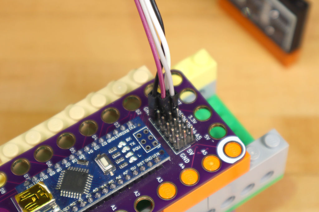
Now you can connect the sensor and motors!
For the sensor: the echo connector should be connected to pin 3 on the board, the trigger connector to pin 5, VCC to 5 V, Gnd to GND. Thus, the sensor will receive power and communicate with the board.
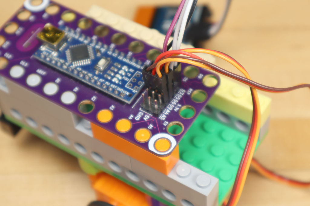
Then you need to connect each of the motors. It's easy to do - brown wires to GND, red wires to 5V, orange wires to D6 for the left motor and D9 for the right.
Step 6: program the Robotics Board
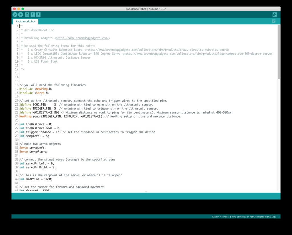
Before the robot can work, the code must be loaded into the microcontroller. Before doing this, make sure you have the latest version of the Arduino IDE installed on your computer .
We have uploaded our code to the repository on GitHub:
github.com/BrownDogGadgets/CrazyCircuits/tree/master/Projects/Avoidance%20Robot
The code is simple, there are many comments in it to make it clear what is responsible for what.
You will also need the NewPing library
bitbucket.org/teckel12/arduino-new-ping/wiki/Home
Step 7: let the robot walk
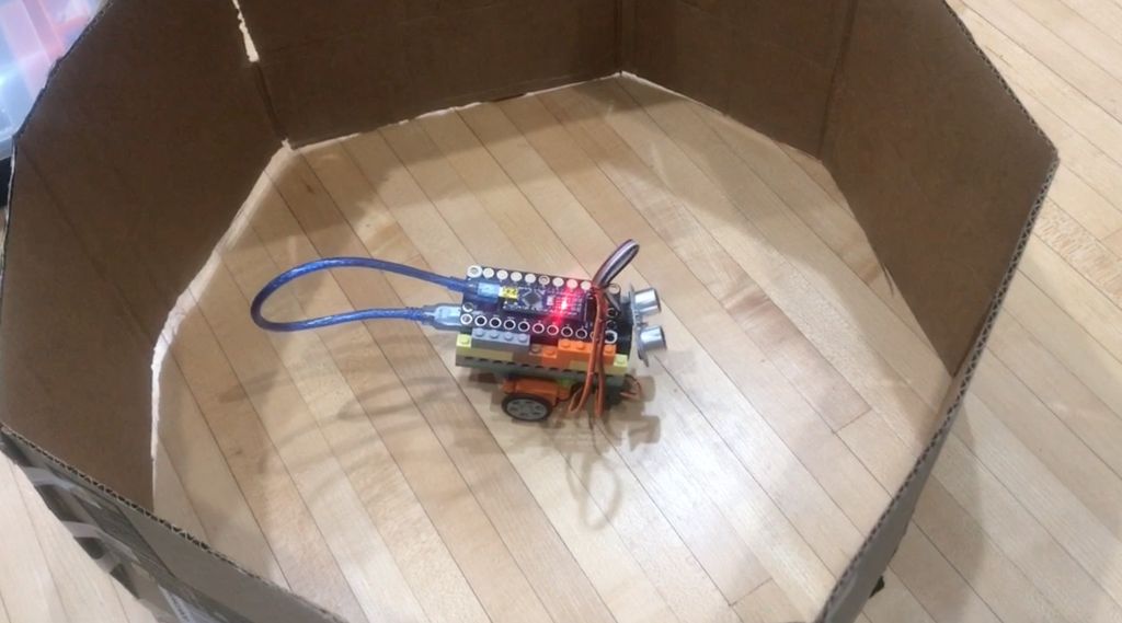
After building a robot and loading the code into it, you can proceed to the tests!
The easiest way is to plug in an external power source and let the robot go forward. If you put your hand in front of him, he has to move back, turn around and go forward again (make sure he doesn't move off the table!)
We built a simple hexagonal "arena" of cardboard so that the robot had a place to ride. Don't be afraid to experiment with what you have.
Step 8: further development
If you are interested in developing this project, here are the questions for you:
- What did you learn while assembling the robot?
- what influenced your choice of parts?
- Will the robot go faster if its wheels are increased?
There are two variables in the code, correcting which, you will change the time the robot rolls back when it detects an obstacle, and the time it will turn. Try swapping goBackwardTime and turnRightTime and see how it affects the robot's behavior.
//

int goBackwardTime = 1000;

//

int turnRightTime = 1000;
See also:
- " Robot control created using LEGO Mindstorms NXT Brick by Wolfram Language language (of Mathematica) »
- " The interaction with the robot based on Lego Mindstorms EV3 designer through RCML »
- « Lego introduced EV3 the Mindstorms »