
Introduction
One of the most famous floppy disk security stories comes from Dungeon Master . This game, released in December 1987, combined the sophisticated physical disk format (fuzzy bits) with covert security checks built into the gameplay itself.
I recommend reading this article , which provides an excellent overview of floppy disks, followed by a very detailed overview of Dungeon Master fuzzy bit protection for the Atari ST. There is also this great article that goes into more detail about the stories surrounding the defense of the Dungeon Master. It contains a quote from one of the Dungeon Master authors:
« , , 40 . , ».
The reason for this high price was most likely due to the timing accuracy required to reliably create fuzzy bits. Back in the days when most of the world measured performance in microseconds, the required accuracy was measured in nanoseconds.
The BBC Micro had a 6502 processor at 2 MHz and took two clock cycles, or 1 microsecond, to execute its simplest instructions. Is there any hope that it will be possible to write fuzzy bits under such restrictions? Let's see how far we can go. This work will be referred to as the "Oiled Otter Project".
To give you a sense of the zeitgeist, here's a picture of a 3.5 "floppy disk duplicator. It's amazing how similar it is to a photocopier, except that you insert discs into the receptacle instead of paper! Looks like Advanced World Products might even have sold you such a machine .

BBC Micro Custom Port
BBC Micro was known for its excellent extensibility, including through the so-called "user port". This port is controlled by the 6522 Versatile Interface Adapter operating at 1 MHz. The port itself has 8 data pins and 2 control pins. These contacts provided a very high degree of control. The data pins could be individually configured as inputs and outputs, and the logic pin levels could be set to high or low.
Why is the user port important to us? We will try to control the disk drive directly through it. By removing the floppy disk controller from the equation, we may be able to get rid of it and gain more direct control over the disk drive and the data streams being transferred.

User port to disk drive
The image above shows my cable connecting the user port to the disk drive. The connectors are standard, and the wires connecting them are just jumpers. I sincerely strive to create something that could be made “in those days”, so I don't use any additional electronics.
The cable is arranged as follows:

The main takeaway from this diagram is that the disk drive interface is probably simpler than one might think. We can control the disk drive and query its important status on just 8 pins. Everything is very simple. Let's say we need to spin the drive, then it is enough to give a low signal to PB0 and PB1. If you want to wait for the disc to rotate to the beginning of the track, then you need to query the logic level on PB6 until we see the signal level change from high to low. For step-by-step movement, it is enough to set the logic level “step in” opposite to “step out”, and then perform a pulsation of a low signal on the contact “step”.
So far so good, we have basic control over the drive, but we haven't recorded anything yet.
Electrical problems
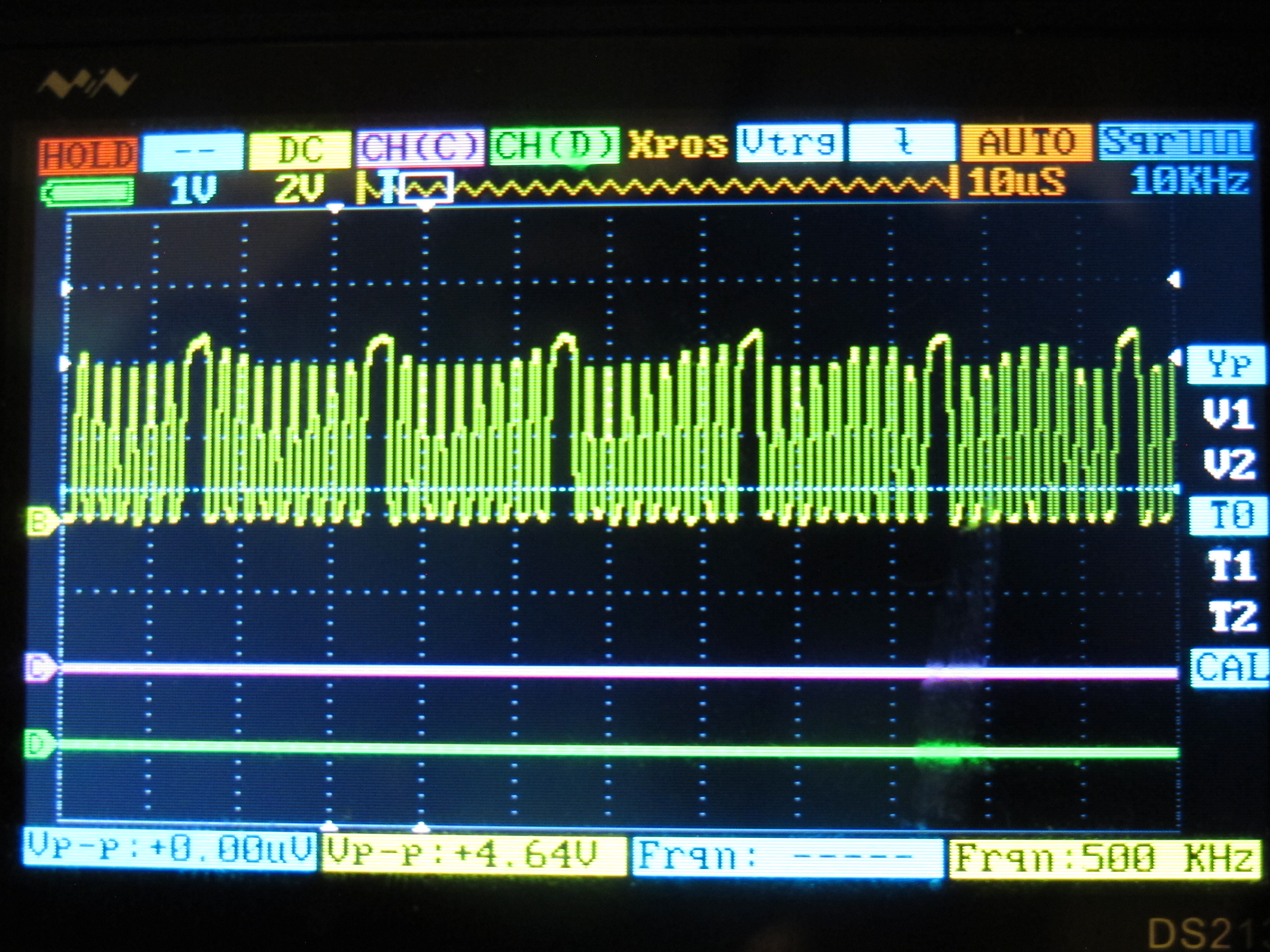
A short digression on electrical problems is imperative, because I ran into them. Connecting random pairs of components can make them work, but sometimes tweaks are required. Here is the voltage range initially observed at the W / DATA pin of the drive:

We are trying to write pulses to a drive with an FM frequency of 250 kHz.
Logic 1 voltage is approximately 3.4 V, and logic 0 voltage is approximately 1.5 V. This is a serious problem! Acceptable TTL voltage levels are well defined:
“The TTL input signal is considered 'low' if it has a voltage between 0 V and 0.8 V relative to the ground pin, and 'high' when it is between 2 V and VCC (5 V). If a voltage signal in the range from 0.8 V to 2.0 V is applied to the input of a TTL element, then the element does not give a specific answer, and therefore the signal is considered "undefined". "
A logic 0 voltage of 1.5 V is considered "undefined" and will not cause any action. Indeed, my drive was not recording anything with this signal.
The problem was resolved by removing the floppy drive cable EOL from the drive . Here is a photo of my drive with the EOL assembly outlined in red:
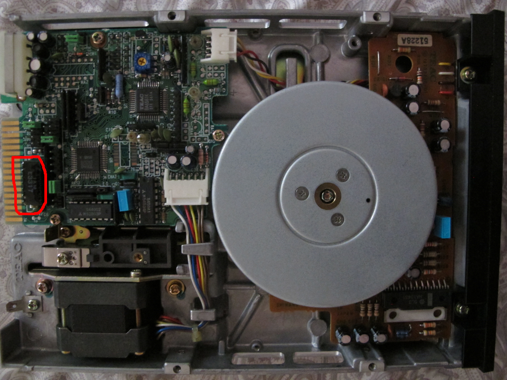
This solves the problem of voltage levels nicely, after which everything works. It looks like many of the BBC Micro's ports other than the disk port do not have enough power to drive the EOL cable. But wait - there was probably some reason for installing this resistor? Yes. Removing it has two tricks:
- Pay attention to the length of the cables. Without an EOL resistor, long cables are prone to signal distortion.
- Watch for voltage levels on unconnected wires. I observed a voltage of 1.32V on the S / SEL actuator pin (side select). This is not normal because this value is also in the TTL uncertainty range. Where will the drive write data? Maybe the top side, maybe the bottom. Or maybe none of them at all! The problem was solved by connecting each significant cable and applying a high or low signal to them.
Need to increase bandwidth
The problem that we have bypassed so far: how to send a signal to the W / DATA pin? This is a "hard" contact. It has high bandwidth and precise timing requirements. Let's stop dreaming about fuzzy bits with nanosecond precision for a second and try writing simple FM pulses to the drive.
Most discs for BBC Micro are in FM (aka DFM, aka single density) encoded at 250 kHz. Recording an FM track is actually quite simple. It is necessary to check if the drive is rotating and if the record flap is open. After that, every 4 microseconds, either we perform W / DATA ripple to low, and then back to high signal (bit 1), or we do not do it (bit 0). Most often every second bit should be 1 (sync bit to maintain timing and sync).
Controlling W / DATA through a processor is a hopeless task. 4 microseconds is 8 processor clock cycles; this is definitely not enough to load a byte, shift it, write 0, and then 1 to the logical levels of the user port. A simple cycle will likely take 12+ microseconds, which is too much. So, to write W / DATA quickly enough, we'll have to use the capabilities of the 6522 VIA chip.
Shift register 6522 VIA
The most obvious candidate for our task is a shift register. The shift register is an 8-bit register. In the corresponding mode, loading the shift register will force the chip to transmit 8 bits sequentially on one of the user port pins. This is great - the bits are processed in parallel with the main processor, so the processor can safely spend time creating a new set of bits to begin shifting.
Unfortunately, I was unable to get this circuit to work. The only shift mode that has the potential to run reasonably quickly is the "system clock shift". The Western Design Center 6522 spec has a nice outline:
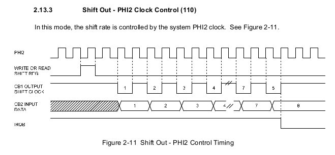
The VIA system clock is 1 MHz, so the offset clock will be 500 kHz and the output bit resolution is 250 kHz. This is just enough. However, I have not figured out how to get the shift clock to work continuously and smoothly. Even after trying accurate timing to reload the shift register, the pin interval of the shift clock always looked like this:
It turns out that in a single shift mode fast enough for our experiments, reloading the shift register causes a delay before continuing with the shift. It doesn't suit us.
6522 VIA Pulse Output Mode
A little known feature of the 6522 is its "pulse output mode". It is not described in the specifications of all 6522 variations, but here is a small entry about it in the MOS Technology specification :

Finally, we have found a specification that accurately describes its behavior. This mode is very interesting for us, because one write operation in VIA promises to lead to two separate actions: a low logic signal is applied to the output pin, and after 1 clock (1 microsecond) it returns to a high signal without any effort on our part. This allows us to use it to drive the 250 kHz output signal. Processor resources are very limited - the loop will not solve the problem in any way, but the linear code block 6502 will be able to cope, for example:
        \ &70 points to &FE60, aka. user 6522 VIA ORB register.
        STA (&70),Y        \ 8 cycles, pulse output
        STA (&70),Y        \ 8 cycles, pulse output
        STA (&70),Y        \ 8 cycles, pulse output
        LDA (&70),Y        \ 8 cycles, do not pulse output
        STA (&70),Y        \ 8 cycles, pulse output
        ...
It will work. The processor has just enough power for this. 8 clock cycles is 4 microseconds, which is the shortest time between disk pulses.
Unfortunately, such an operation is extremelyactively uses memory. Each encoded FM bit requires 2 bytes of 6502 line code. Each significant data bit is two FM bits because every other bit is sync. A track is 3125 bytes long, so 3125 * 8 * 2 * 2 == 100 kB of line code is required. BBC Micro has 32KB of RAM, so we're out of luck here. Single (small) sectors can be written, including powerful new disk protection mechanisms. But we will not be able to write large (1024 bytes) sectors or full tracks. Both of these operations are required to write large numbers of discs correctly. Moreover, the resolution of timings is 1 microsecond, which is not enough for recording many more complex protections and disc surfaces.
We can be happy that we managed to get at least something to work, given such restrictions, but this solution does not completely suit us.
Help from a non-promising output port
Fortunately, I talk to smart people like the Bitshifters Collective . (Go check out their latest demo, Evil Influences !) In a conversation on Slack, Tom Seddon (the author of the b2 emulator ) suggested ... using the RGB port output (?)
Video to disk adapter cable ... you don't see that on Amazon every day.
At first I laughed at this idea, but the more I thought about it, the more likely it seemed to me. The BBC Micro uses the 6845 video chip for timings . Like the 6522, it is a moody processor, but at least its features are well deciphered thanks to the Bitshifters demo that exploits the 6845 mercilessly. Also, I did reverse engineering to get the jsbeeb emulatorcorrectly emulate Hitachi 6845. Let's take a look at the work of Oiled Otter in this video, and then tell us what we saw:
Everything works thanks to the unusual configuration of the 6845 chip. The 6845 runs at 1 MHz and the frame timing is set to have one raster line at 32 microseconds / 32 bytes per "frame". At each frame output, the 6845's video memory registers are overwritten to retrieve the next 32 bytes from a potentially different location. That is, every 32 microseconds, a different output pattern is selected from the output pattern table. We configured the RGB pins to transmit 8 pixels per microsecond, which is 256 per output pattern. This gives us a huge number of different possible output patterns. But since we are recording 32 microsecond chunks of FM disk encodings, only a few patterns are suitable for us. In 32 microseconds, we can fit 8 FM pulses / bits. 4 bits will be sync, and usually they are all 1.4 bits will be data bits and there are only 16 combinations of them.
For example, if we write a nibble of data 0x5, then the 32 microsecond output should look like this:

Video data will be in the form 00FFFFFFFFFFFFFF00FFFFFF00FFFFFF00FFFFFFFFFFFFFF00FFFFFF00FFFFFF. The first, second, fourth and fifth 00 are sync bits. Between the sync bits is the data bit pattern 0101, or 0x5.
CPU and memory constraints are well balanced. Ultimately, this circuit is similar to the one we would try with the shift register VIA if it worked: some small coprocessor (video chip) handles the transmission of a set of FM bits, and the central processor is free to load and provide the next pattern. The memory requirements are quite reasonable. A table of the required output fragments for 32 microseconds, thanks to a special linear addressing mode, fits well into 1024 bytes. The list of search indexes for the entire track is roughly 12KB, so everything fits perfectly into the 32KB of BBC Micro RAM.
Features of BBC Micro / 6845
Last character / column 6845
Of course, to get this to work, you have to run into some "fun" features. The first is a feature of the 6845, which causes it to output black for the last character of each bitmap line. This is the curse of the demo developers, and now it seems, the disc researchers too. Here is a slide from a recent talk in which I demonstrated this problem:

On the left is an effect from the demo, ruined by vertical black bars caused by the "last black character / column" problem. Multiple 6845 raster lines fit in a single raster pass, and unfortunately black stripes appear unintentionally. With disc control, the effect is much worse: the black bars are replaced with unwanted pulses, which are written to the disc.
The image of the solution is shown on the right: the wave transmitted to the disk is simply inverted. It is now normal that the last column will always be black (shown with an orange outline), because a zero is always required there. Strictly speaking, this violates the timing requirements of some disk drives for pulsing low W / DATA signals. Here is a diagram of the timing of a drive from that era, Mitsubishi M4852 / M4853 :
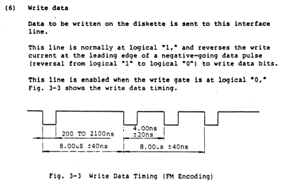
According to this scheme, logic 0 should be held up to 2100 ns. With an inverted waveform, expect 3000 ns or more. However, the drives I have only care about falling data pulses, not their duration. This is not surprising. There were a couple of tricks I could have done to avoid the 6845's quirks and ensure the duration times are in line with the spec, but that turned out to be optional, so I didn't do it.
DRAM
corruption DRAM decay is a nightmare. It happens when we fail to update DRAM in time. Quoting from the Wikipedia article on updating memory :
"This process is performed automatically in the background by an electronic memory circuit and is invisible to the user."
This is true for modern systems, but not for the BBC Micro. On BBC Micro, the DRAM upgrade is a side effect of the video subsystem. It takes advantage of the property that standard screen modes iteratively traverse all DRAM lines in a short amount of time. You probably already guessed where this is going - our special video mode, used to display frames at 32 microseconds, is not the standard screen mode. It does not guarantee that it will bypass all DRAM lines, so DRAM corruption occurs! DRAM corruption is no joke. Due to unplanned DRAM corruption, I was losing various programs and disc content. I'll show you, for a laugh, a BASIC program that causes DRAM damage to itself in just a split second:

The sad thing about DRAM corruption is that if it befell you, you can easily lose data.
On the other hand, if you expect DRAM corruption, you can usually bypass it with ease. In the case of Oiled Otter, there are various critical cycles where the 6845 is in an unusual state. To save the DRAM update at each of these cycles, a manual increment of retrieving data from memory works.
Opened opportunities
Now that we have a working disk write system bypassing the floppy controller, what can we do with it? In the video above, we have already demonstrated its ability to burn random FM encoded discs.
But in this study we were very lucky. Due to the shortcomings of the VIA shift register, we had to look for a solution with video output pins, and we got access to a much finer resolution of the timings on the W / DATA pin . We are using the MODE4 of a BBC Micro computer using an 8 MHz pixel clock. This means you can output black or white pixels every 125 ns by switching write pulses with 125 ns resolution... If we wanted to spend a little more extra memory (which we have) on larger tables, we could use MODE0, which uses a 16 MHz pixel clock, which provides a resolution of 62.5 ns. I made sure that 125ns is good enough for all the disc protections tested, but it's great that we still have some wiggle room.
Long Track Protection
My favorite disc protection is long track protection. She was popular during the Amiga... I don't think it was ever used on the BBC Micro. I like long track protection because it is very fundamental: the floppy disk controller has a lot of tolerance for varying write speeds (because disk drives spin at different speeds), but it only writes at one correct speed.
More complex protection with long tracks is to write two sectors on one track, in which one of the sectors is written at a higher speed. The copy protection check is the time it took to read these two sectors. The sector written at a higher speed should be read much faster.
Can Oiled Otter record such a track? Yes, and pretty easy. Given the 125 ns output resolution, it is easy to create multiple output table entries similar to normal, but with 125 nanoseconds cut out of each 1 microsecond. Here's a video of creating long-track protection and checking disk reads:
Protection with fuzzy bits
Probably, it is high time for us to return to where we started: protection with fuzzy bits. Can Oiled Otter create fuzzy bits on 1981 hardware? Let's try. Here is an image of the results of a pair of sector reads after it was written by the FUZZ command of the Oiled Otter system.

The FUZZ instruction writes the 0x8 nibble and the data bit is progressively set aside in 125 ns increments. This is similar to the description of how the fuzzy bits of the Dungeon Master were recorded. As you can see from the screenshot, the 0x88 data bytes soon begin to be read incorrectly and in a non-deterministic manner. But the variance is not 100% random like the weak bits - variance is whether the 0x8 bit is written late enough to have a chance of being missed. If it's omitted, we can still see that there are patterns and logic in this madness.
The results presented above are an application of the fuzzy bit principles to FM encoded data. In FM encoding, each data bit is interleaved with a sync bit. This leads to the fact that sometimes clock bits sneak into the data stream (see bytes 0xFF in the first run - most likely they are clock bits). Dungeon Master's defense uses fuzzy bits in conjunction with MFM. This leads to a simpler situation where fuzzy bits move between two valid data bit encodings and do not touch the sync bits! Of course, Oiled Otter can write MFM, GCR and any other encoding you can think of. All these are just different protocols of one fundamental primitive - the ability to transfer a pulse to the drive at any time with good resolution.
To evaluate it correctly, we will give the view of the fuzzy bits on the disk from the oscilloscope. The maxima are rather uneven, and when the two pulses are very close to each other (1 microsecond or so, too close by any standard encoding), the magnetization reversal force recognized by the drive even begins to wane.

Mission accomplished
We got the ability to record disk pulses with a resolution of 125 ns. This is perfectly sufficient to create complex disc protections, including long tracks, weak bits, and fuzzy bits. Not bad for 1981 hardware with the fastest command execution speed of 1 microsecond!
See also: