To clarify, abstractions such as dividing these positions and rendering functionality into separate classes are important in real-world applications. However, these abstractions scatter the code in different areas and add redundancy due to the boilerplate and data transfer between logical units. I find it most convenient to study a topic in a linear flow of code, in which each line is directly related to this topic.
First, I need to thank the creator of the tutorial I used . Taking it as a basis, I got rid of all abstractions until I got the "minimal viable program". Hopefully it helps you get started with modern OpenGL. Here's what we will do:

Equilateral triangle, green at the top, black at the lower left, and red at the lower right, with colors interpolated between the points. A slightly brighter version of the black triangle [ translation in Habré].
Initialization
In WebGL, we need
canvasto draw. Of course, you will definitely need to add all the usual HTML boilerplate, styles, etc., but canvas is the most important thing. After the DOM has loaded, we can access the canvas using Javascript.
<canvas id="container" width="500" height="500"></canvas>

<script>
  document.addEventListener('DOMContentLoaded', () => {
    // All the Javascript code below goes here
  });
</script>
By accessing the canvas, we can get the WebGL rendering context and initialize its clear color. Colors in the OpenGL world are stored as RGBA and each component has a value from
0to 1. The clear color is the color used to draw the canvas at the start of each frame, redrawing the scene.
const canvas = document.getElementById('container');
const gl = canvas.getContext('webgl');

gl.clearColor(1, 1, 1, 1);
In real programs, initialization can and should be more detailed. In particular, mention should be made of the inclusion of a depth buffer that allows you to sort geometry based on Z coordinates. We will not do this for a simple program with just one triangle.
Compiling shaders
At its core, OpenGL is a rasterization framework where we have to decide how to implement everything other than rasterization. Therefore, at least two stages of code must be executed in the GPU:
- A vertex shader that processes all the input data and outputs one 3D position (actually a 4D position in uniform coordinates ) for each input.
- A fragment shader that processes each pixel on the screen, rendering the color that the pixel should be painted with.
Between these two stages, OpenGL gets the geometry from the vertex shader and determines which screen pixels are covered by that geometry. This is the rasterization stage.
Both shaders are usually written in GLSL (OpenGL Shading Language), which is then compiled into machine code for the GPU. The machine code is then passed to the GPU so that it can be executed during the rendering process. I won't go into GLSL in detail because I only want to show the very basics, but the language is close enough to C to be familiar to most programmers.
First, we compile and pass the vertex shader to the GPU. In the fragment shown below, the shader source code is stored as a string, but can be loaded from other places. Finally, the string is passed to the WebGL API.
const sourceV = `
  attribute vec3 position;
  varying vec4 color;

  void main() {
    gl_Position = vec4(position, 1);
    color = gl_Position * 0.5 + 0.5;
  }
`;

const shaderV = gl.createShader(gl.VERTEX_SHADER);
gl.shaderSource(shaderV, sourceV);
gl.compileShader(shaderV);

if (!gl.getShaderParameter(shaderV, gl.COMPILE_STATUS)) {
  console.error(gl.getShaderInfoLog(shaderV));
  throw new Error('Failed to compile vertex shader');
}
It is worth explaining some of the variables in the GLSL code here:
- (attribute)
position. , , . - Varying
color. ( ) . . -
gl_Position. , , varying-. , ,
There is also a uniform variable type , which is a constant across all vertex shader calls. Such uniforms are used for properties like a transformation matrix, which will be constant for all vertices of one geometric element.
Next, we do the same with the fragment shader - we compile it and transfer it to the GPU. Note that the variable
colorfrom the vertex shader is now read by the fragment shader.
const sourceF = `
  precision mediump float;
  varying vec4 color;

  void main() {
    gl_FragColor = color;
  }
`;

const shaderF = gl.createShader(gl.FRAGMENT_SHADER);
gl.shaderSource(shaderF, sourceF);
gl.compileShader(shaderF);

if (!gl.getShaderParameter(shaderF, gl.COMPILE_STATUS)) {
  console.error(gl.getShaderInfoLog(shaderF));
  throw new Error('Failed to compile fragment shader');
}
Further, both the vertex and fragment shaders are linked into one OpenGL program.
const program = gl.createProgram();
gl.attachShader(program, shaderV);
gl.attachShader(program, shaderF);
gl.linkProgram(program);

if (!gl.getProgramParameter(program, gl.LINK_STATUS)) {
  console.error(gl.getProgramInfoLog(program));
  throw new Error('Failed to link program');
}

gl.useProgram(program);
We tell the GPU that we want to execute the above shaders. Now all we have to do is create the incoming data and let the GPU process this data.
Sending incoming data to GPU
Incoming data will be stored in GPU memory and processed from there. Instead of making separate draw calls for each piece of incoming data, which transfer the corresponding data one chunk at a time, all of the incoming data is transferred in its entirety to the GPU and read from there. (Old OpenGL passed data on individual elements, which slowed down performance.)
OpenGL provides an abstraction called Vertex Buffer Object (VBO). I'm still figuring out how it works, but we will end up doing the following to use it:
- Store the data sequence in the central processing unit (CPU) memory.
- Transfer bytes to GPU memory through a unique buffer created with
gl.createBuffer()and anchor pointsgl.ARRAY_BUFFER.
For each variable of input data (attribute) in the vertex shader, we will have one VBO, although it is possible to use one VBO for several elements of the input data.
const positionsData = new Float32Array([
  -0.75, -0.65, -1,
   0.75, -0.65, -1,
   0   ,  0.65, -1,
]);

const buffer = gl.createBuffer();
gl.bindBuffer(gl.ARRAY_BUFFER, buffer);
gl.bufferData(gl.ARRAY_BUFFER, positionsData, gl.STATIC_DRAW);
Typically we define the geometry with whatever coordinates our application understands, and then use a set of transforms in the vertex shader to map them to the OpenGL clip space . I will not go into detail about the truncation space (it is associated with homogeneous coordinates), while you only need to know that X and Y change in the range from -1 to +1. Since the vertex shader simply passes the input as it is, we can set our coordinates directly in the clipping space.
Then we will also bind the buffer to one of the variables in the vertex shader. In the code, we do the following:
- We get the variable descriptor
positionfrom the program created above. - We instruct OpenGL to read data from the anchor point
gl.ARRAY_BUFFERin groups of 3 with certain parameters, for example, with an offset and a stride of 0.
const attribute = gl.getAttribLocation(program, 'position');
gl.enableVertexAttribArray(attribute);
gl.vertexAttribPointer(attribute, 3, gl.FLOAT, false, 0, 0);
It's worth noting that we can create a VBO this way and bind it to a vertex shader attribute because we execute these functions one after another. If we were to separate the two functions (for example, create all VBOs in one pass, and then bind them to separate attributes), then before mapping each VBO to the corresponding attribute, we would need to call each time
gl.bindBuffer(...).
Rendering!
Finally, when all the data in the GPU memory is prepared as needed, we can tell OpenGL to clear the screen and run the program to process the arrays we have prepared. As part of the rasterization step (determining which pixels are covered by the vertices), we tell OpenGL to treat vertices in groups of 3 as triangles.
gl.clear(gl.COLOR_BUFFER_BIT);
gl.drawArrays(gl.TRIANGLES, 0, 3);
With such a linear scheme, the program will be executed in one go. In any practical application, we would store data in a structured way, send it to the GPU as it changes, and render it every frame.
To summarize, below is a diagram with a minimal set of concepts that are required to display our first triangle on the screen. But even this scheme is greatly simplified, so it is best to write the 75 lines of code presented in this article and study them.
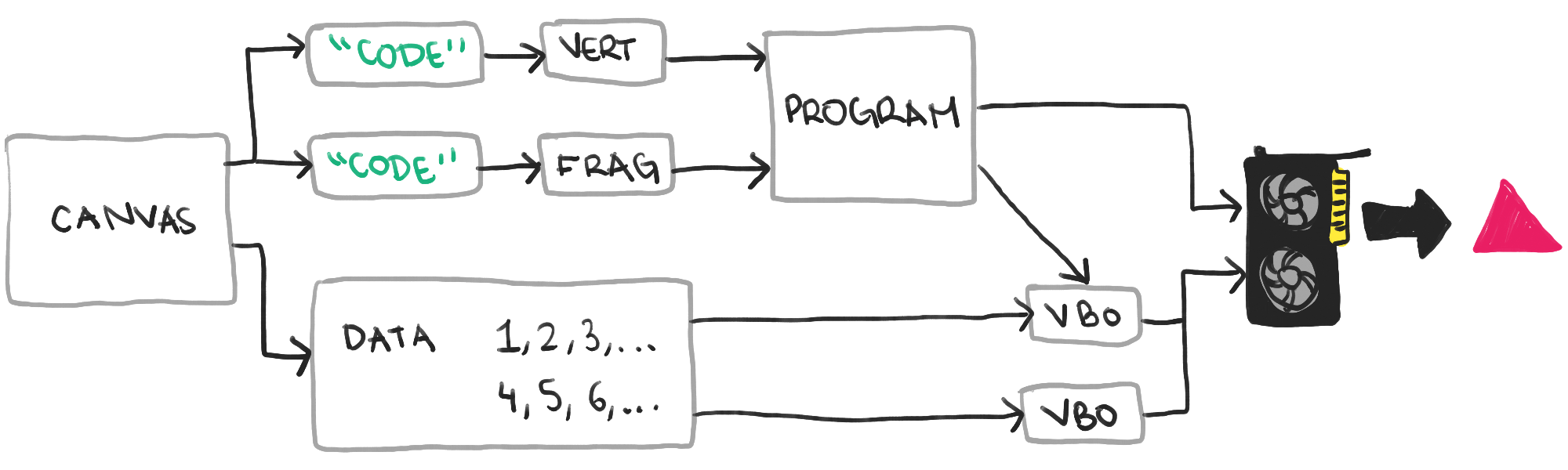
The final highly simplified sequence of steps required to display a triangle
For me, the hardest part of learning OpenGL was the sheer amount of boilerplate required to display the simplest image on the screen. Since the rasterization framework requires us to provide 3D rendering functionality, and the communication with the GPU is very large, many concepts have to be studied directly. Hopefully this article has shown you the basics in a simpler way than they appear in other tutorials.
See also:
- " WebGL for everyone "
- " WebGL Application Performance "
- " Five WebGL Presentations That Amazing "
See also:
- " WebGL for everyone "
- " WebGL Application Performance "
- " Five WebGL Presentations That Amazing "