 "
"
We are launching a series of useful articles devoted to nanoCAD utilities. They will make the process of preparing drawings easier and faster.
You will learn:
• how to use the Advanced nanoCAD tool for express editing;
• how to quickly replace a word using the Find and Replace command ;
• how to connect dwg tables broken into primitives using the Recognize tables command ;
• how to export part of the graphics to a new file in one click ;
• what are the ways to create an array of objects.
Follow the channel. And today we will discuss Additional nanoCAD tools .
Additional nanoCAD tools are tools similar to the most popular and demanded Express Tools, implemented as part of a foreign analogue. A distinctive feature of these utilities in nanoCAD is that they are installed by default, while the user of a foreign solution has to control their appearance in the program interface during installation. The add-on toolkit includes 10 of the most commonly used utilities. Next, we will consider the functionality of each of them and give examples of how they work.
In the classic nanoCAD interface, additional tools are located in the Edit → Additional Tools menu (Fig. 1). In tape, they are divided into different groups depending on the objects with which this or that utility works.

. 1. nanoCAD
nanoCAD:
1.
Command line: BREAK ATRBLOCK (BURST) This
command allows you to extract text information from the attributes of blocks when you break them. A significant difference from the similar Explode command is that when using the last value of the block attributes, only the names are deleted and remain. And the BREAK ATRBLOCK command converts block attribute values to single or multiline text. The values of the field inserted when the block attribute was created are also flushed into the text. Hidden block attributes are not converted.
The order of command execution:
• select a block with attributes (Fig. 2).
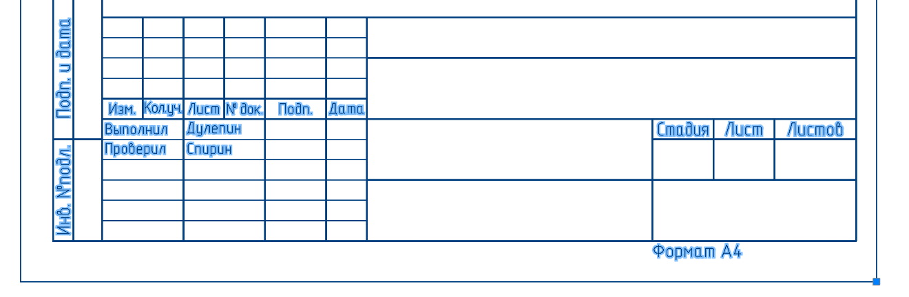
. 2.
The attributes presented in this block are shown in Fig. 3;

. 3.
• run the command Convert block attributes to text .
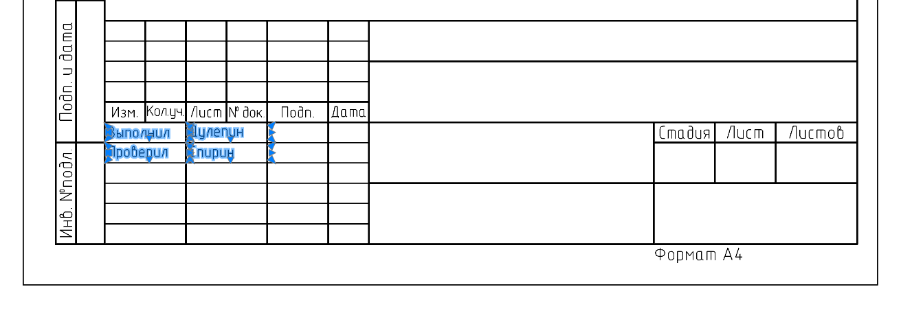
. 4.
As seen in Fig. 4, the block attributes were converted to Mtext and we can continue editing.
The result of the Stakeout command with the same block is shown in Fig. five.
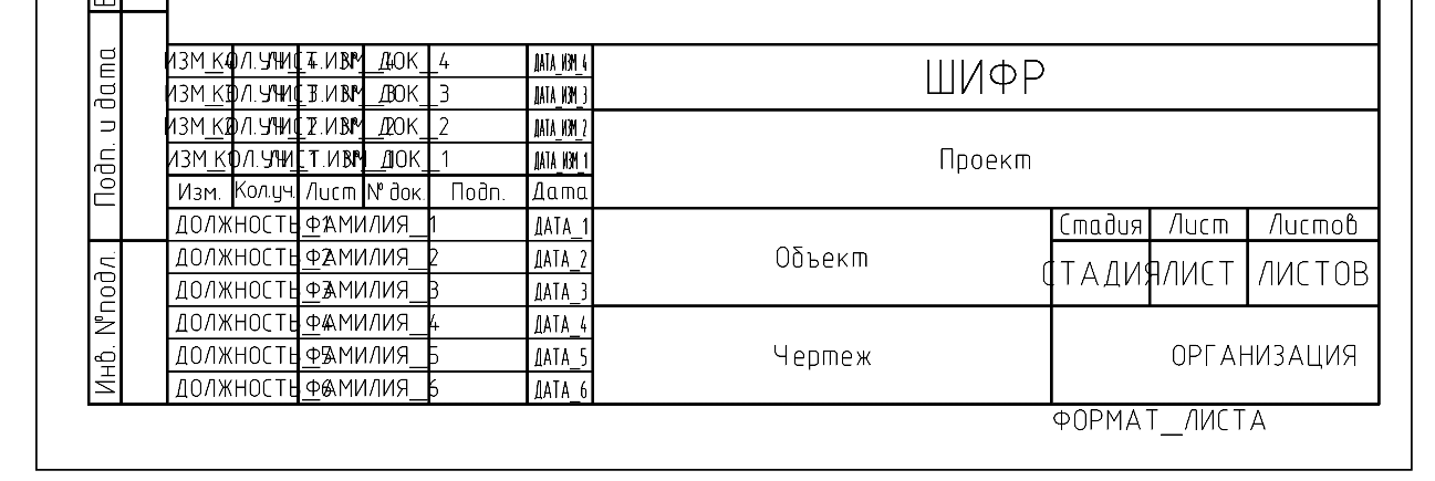
. 5.
Utility 2. Convert Text to Mtext
Command line: TEXTvMTEXT, T2MT (TEXT2MTEXT, T2MT) This
command converts selected single-line text objects to multi-line text. When converted, single-line text objects are removed from the document and inserted into a single multi-line text object. At the same time, the values of height, color, compression ratio, and angle of inclination of text objects are saved in multiline text.
The order of command execution:
• select single-line texts (fig. 6);

. 6.
• call the command Convert Text to Mtext (Fig. 7).

. 7. ,
Utility 3. Text alignment
Command Line: TEXT (TJUST) This
command allows you to change the alignment points for a text object without moving the text.
The order of command execution:
• select a text object (fig. 8);

. 8.
• run the Align Text command and select the required alignment method in the command line or the context menu (Fig. 9).

. 9.
Alignment examples are shown in Fig. 10 and 11.

. 10. ()

. 11. ()
Utility 4. Change the case of text
Command line: TREGISTER (TCASE) This
command allows you to edit the case of words, sentences and paragraphs of the selected text.
The order of command execution:
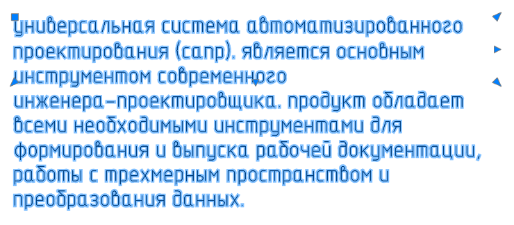
• select a piece of text (fig. 12);

. 12.
• run the Change text case command and set the required parameter in the Text case window (Fig. 13). Click OK .

. 13.
The command execution result is shown in Fig. fourteen.
. 14.
Utility 5. Stretch or shrink text
Command line: TEXTFIT This
command allows you to stretch or shrink a single line of text with the ability to move it.
Command execution order:
• run the command;
• select a text object. When you select an object, the initial (lower left) point is automatically captured (Fig. 15);
. 15.
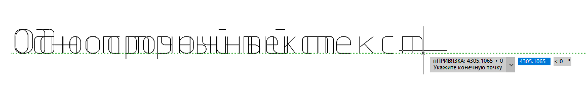
• specify the second point on the screen. The text either automatically fits into the specified boundaries, or stretches (Fig. 16).

. 16.
Utility 6. Text splitting
Command line: EXPLODETEXT, TXTEXP
The command allows you to split text objects into separate components (lines, polylines). In the process of its execution, you can adjust the parameters for both the staking out results and the original objects. Applying the command to preselected text objects will split according to the previously set (or default) settings.
The order of command execution:
• select a text object (fig. 17);

. 17.
• run the command Split Text . As a result, you will receive text in the form of lines and polylines (Fig. 18).

. 18.
When you run the command without selecting text, the parameters of the source objects and breakdown elements can be configured in the context menu or in the command line (Figure 19).

. 19.
Utility 7. Split Geometry
Command line: EXPLODEGEOMETRY The Explode Geometry
command, unlike the EXPLODE command, separates complex objects into primitives along the entire depth of nesting levels. For example, it will immediately split several nesting blocks into their constituent segments, arcs, polylines - without the need to repeatedly call the command.
The order of command execution:
• select an object (fig. 20);

. 20.
• call the Split Geometry command . The "ellipse" object will be converted to a 2D polyline (Fig. 21).

. 21. 2D-
Utility 8: Simplify Spline
Command Line: SIMPLIFYSPLINE This
command allows you to optimize a spline by controlling the accuracy of its approximation and specifying the maximum number of points.
The order of the command execution:
• select a spline (fig. 22);

. 22.
• call the Simplify spline command ;
• in the command line, specify the accuracy and maximum number of points (Fig. 23);

. 23.
• press Enter .
The command execution result is shown in Fig. 24.

. 24.
Utility 9. Breakdown of proxy objects
Command line: RZBPROXY (XPROXY)
The command is intended for splitting proxy objects with graphical representation into ordinary objects. Pre-selection of objects is allowed.
The order of command execution:
• call the Split proxy objects command .
If there are no selected objects, the command will display a request (Fig. 25).

. 25. -
In response, you can select objects or specify an option. The Drawing option is used to select all proxy objects with graphics in the drawing, including objects on other tabs of the drawing that cannot be selected in any other way. After specifying this option, the system will perform the split and report the results (Figure 28).
In fig. 26 shows the selected proxy objects.

. 26. -
After executing the command, the proxy object takes the form shown in Fig. 27.

. 27. -

. 28. -
Utility 10. Removing proxy objects
Command line : RMPROXY
The command is designed to delete proxy objects. Pre-selection of objects is allowed.
The order of command execution:
• run the command Delete proxy objects ;
• select proxy objects.
If there are no selected objects, the command will display a request (Fig. 29).

. 29. -
In response, you can select objects or specify the desired option.
Option ? displays a request to change the method for selecting objects (Fig. 30).

. 30.
The Drawing option is used to select and delete all proxy objects in the drawing, including objects on other tabs in the drawing.
Option Non-graphicproxy is designed to delete only proxy objects without graphics, which cannot be selected in any other way.
If you specify the required option, the system will delete it, reporting the number of found and deleted proxy objects (Fig. 31). An example of command execution is shown in Fig. 32 and 33.
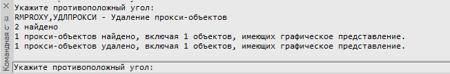
. 31. -

. 32.

. 33.
Conclusion
Additional nanoCAD tools are utilities for drawing management and editing. All of them are distinguished by their efficiency and simple algorithm of use.
At the nanoCAD forum, users are given the opportunity to discuss the existing nanoCAD functionality and, if necessary, propose a new one. Follow the link and test nanoCAD Pro for free for 30 days with the maximum number of modules and capabilities.
Articles related to this
Tatiana Vaskina,
technical specialist of
JSC "Nanosoft"