
Translated from instructables.com, author of the project: Matlek
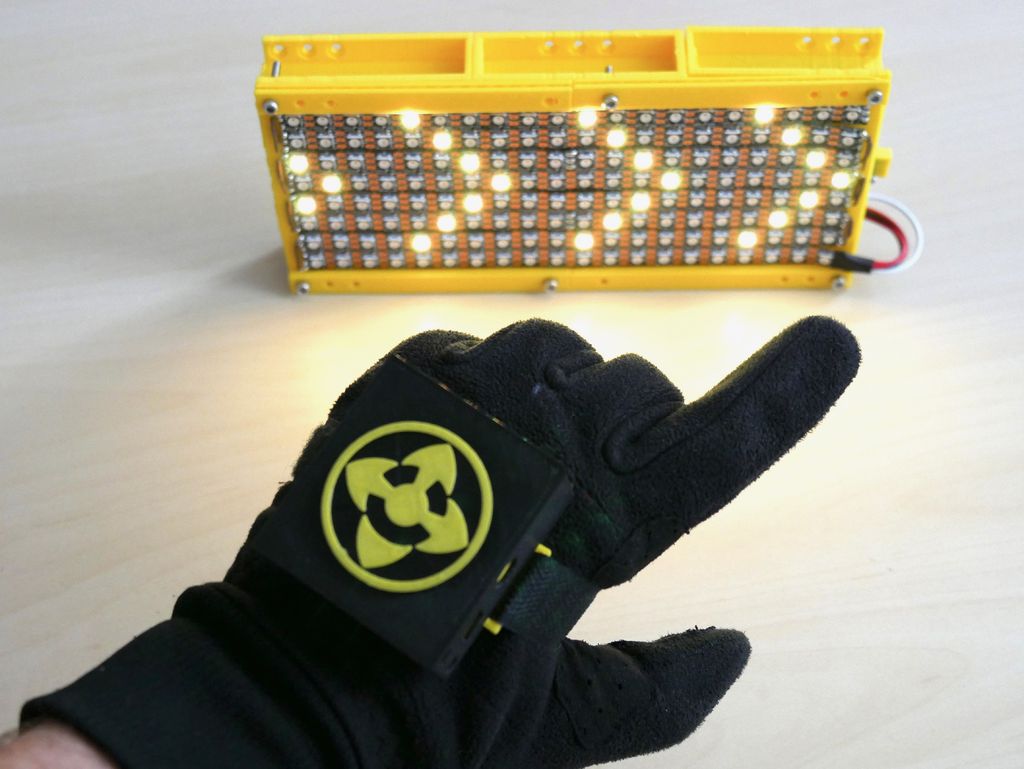
In this article I will describe in detail the process of making a "smart glove" and its LED panel, designed to increase the safety of cyclists and other people traveling on the road. First, you can see a small demonstration of how it works:
How it works
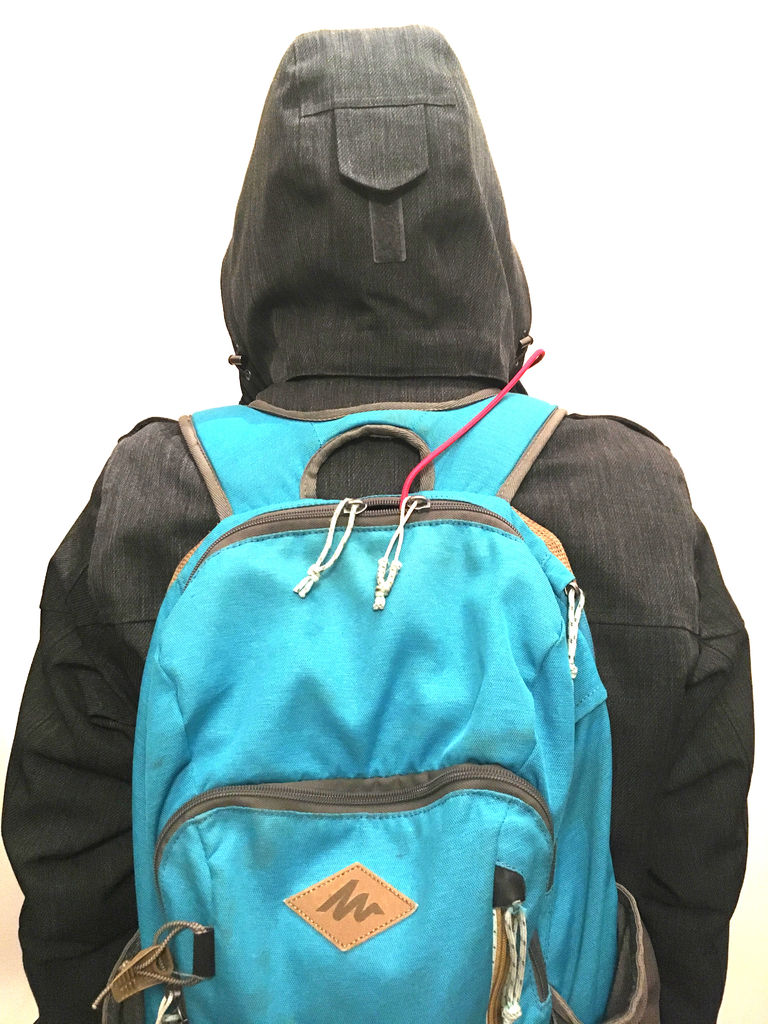
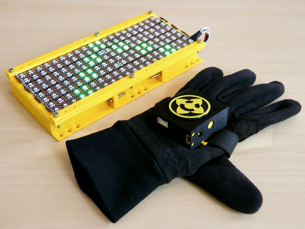
The glove contains an Arduino board that collects data from the gyroscope and accelerometer. The code uses the tinyML model of "tiny machine learning" and recognizes gestures: every movement of the hand is analyzed and turned into a signal (hand tilts left, right, forward, backward, etc.). The signal is sent via Bluetooth (BLE) to another microcontroller to which an LED matrix is connected (which, for example, can be attached to a backpack). According to the received signal, the matrix outputs certain sequences of characters - so that other riders and cyclists can understand what the cyclist is going to do (for example, it can be arrows to the left, right, or text).

Origin of the project
Firstly, I ride my bike to work, and spend more than an hour a day in the saddle (traveling about 22 km). It is always interesting, but I live in one of the most populous cities in France, where accidents involving cars and cyclists often occur. Also Marseille is the worst city for cyclists in France - there is a desperate shortage of bike paths . Therefore, this project is dedicated to both increasing the safety of cyclists and trying to draw the attention of city authorities to this problem.
Secondly, this project will help all members of the movement to communicate and better understand each other. From my point of view, most of the troubles that occur on the road are due to the fact that some road users misunderstood others, which resulted in fear and then aggression. I would like such a device to help traffic participants better understand each other. The arrows show the direction, and you can also display the text by letter (however, I fully and completely advocate polite and constructive inscriptions, in order to avoid conflicts).
Why Smart Glove?
I started work on the project in the winter and the cold weather motivated me to attach the device to my glove. But I quickly realized that the idea was not very good, because in our area it is quite hot in summer. So I decided that it would be best to place the device in a box and fasten it to my arm. But since I didn't know how to name it differently, I decided to leave the word “glove” in the title.
"Smart" comes from the machine learning technique that I used in this project.
Inspiration
The project is basically a mixture of two other projects. I didn’t start from scratch, but used their best practices, which I then developed further. Here's what I was inspired by when developing:
- gesture recognition with Arduino Nano 33 BLE SENSE.
- not a specific project, but the concept of using LED arrays for cyclists. There are a lot of such projects - some use backpacks with integrated panels, others just offer a ready-made matrix that can be placed anywhere. In any case, these LED matrices are controlled by a remote control, not gesture recognition.
Components
For 3D printing - a 3D printer or access to one.
Electronics
- Arduino Nano 33 BLE SENSE;
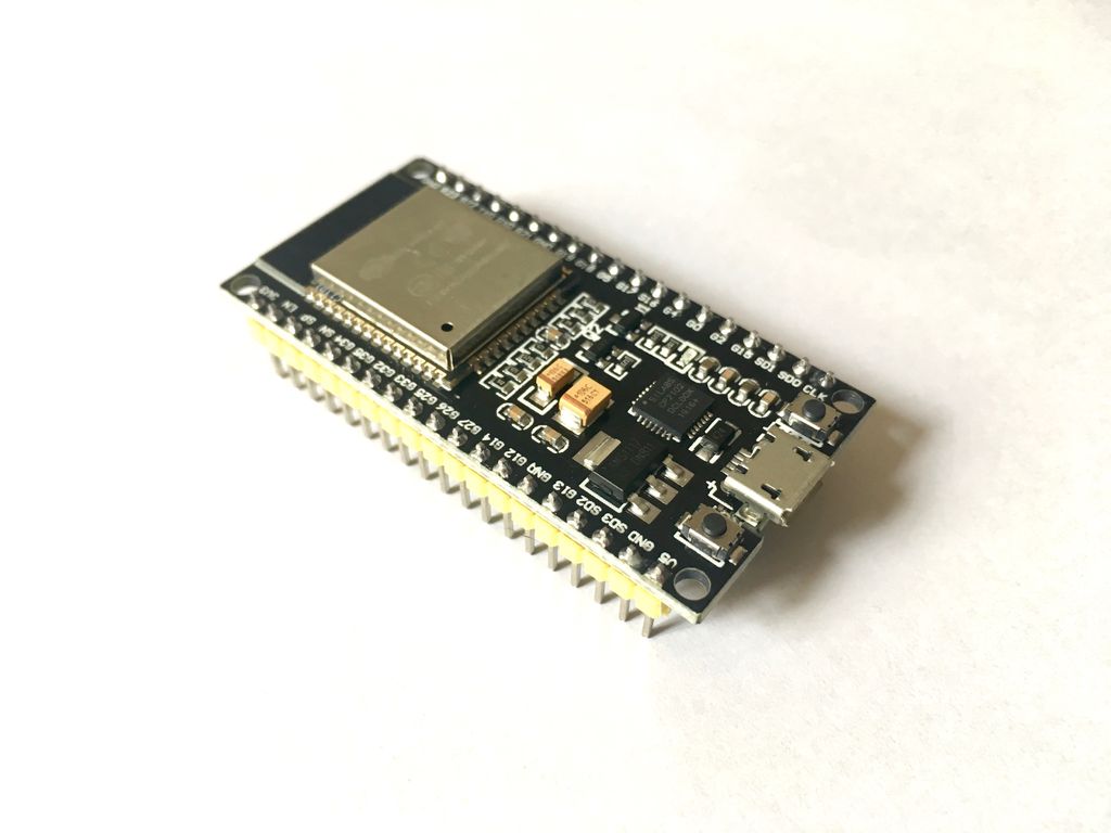
- Another MI with BLE (Arduino Nano 33 BLE, Arduino 33 BLE SENSE, Arduino nano 33 IOT, ESP32, etc.). I decided to use an ESP32 board.
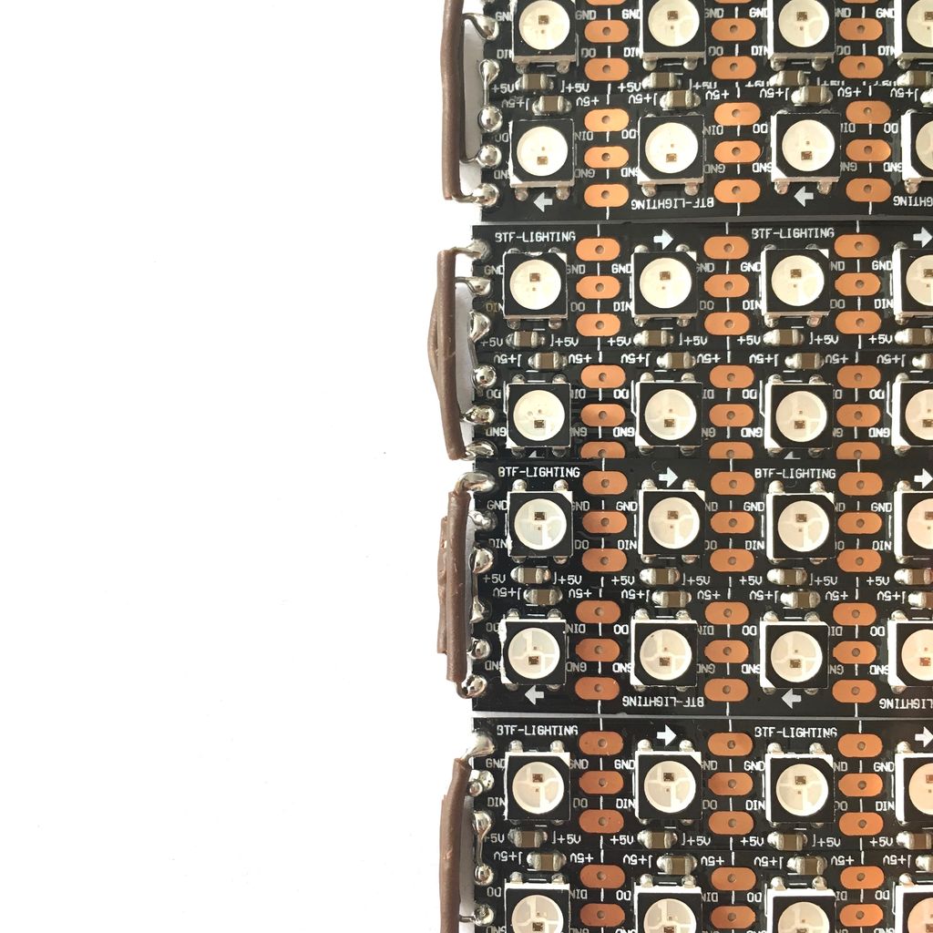
- LED strip (WS2812B). I used 160 LEDs to create a 20x8 matrix;
- 4-level buffer from 3V to 5V: 74AHCT125.
- Capacitor 1000 uF.
- SPST switches, 3 pcs.
- Bread board.
- Wires.
- Battery 9 V.
- External battery.
- 3.
- -.
1: (, )

After reading an article on Arduino and machine learning, I decided to give it a try too. Since there have been several new Arduino Nano boards lately, I made a comparison plate to make the best choice before buying.

All the boards are interesting, but I could use only one for gesture recognition - Arduino Nano 33 BLE SENSE. Only she has the right sensors and Tensorflow Lite support. Another interesting point is that the Arduino Nano 33 IOT, BLE and BLE SENSE boards have their own Bluetooth, so any of them can be used on the LED matrix to receive BLE signals.
The code loaded into the board is based on many different Arduino programs I found during development. Therefore, before starting work, I decided to test them with the examples I found.
Let's play with BLE
In this project, Bluetooth communication is critical because this is how the signal is sent from the sensors to the LED array. Before that, I had never connected two Arduino boards over BLE. So I practiced with the following examples from the ArduinoBLE library :
- The LedControl sketch used with the Arduino Nano 33 BLE Sense board and a button with a pull-up resistor connected to pin 2. The example polls the BLE peripherals until it finds a service with UUID 19b10000-e8f2-537e-4f6c-d104768a1214. After detecting it and establishing a connection, it will remotely control the peripheral BLE LED by pressing a button.
- Sketch for LED and Arduino Nano 33 IoT.
Unfortunately, I had a lot of problems with the sketch for the LED - 3 boards “broke” while loading it. I have no idea what the problem was, but I decided to replace the Arduino board with another MI with BLE - the ESP32 board. With the new board, I used the following:
- BLE_write sketch from BLE ESP32 ARDUINO library. I added a few changes to make it work with the Arduino Nano 33 BLE SENSE board. In step 10, you can compare the BLE_write sketch and the Smartglove_BLE_LED-matrix sketch that I wrote and uploaded.
Let's play with the built-in RGB LEDs
Did you know that the Arduino Nano 33 BLE SENSE board has built-in RGB LEDs? In this project, they will be useful to check the correct operation of gesture recognition. We have to verify that the signal has been sent to the LED array - however, since the panel is most likely on the back of the cyclist, it will be difficult for him to understand that gesture recognition worked and the signal was sent.
There was nothing complicated here, I just tweaked the Blink example a bit . The code shows that the red LED is on pin 22, green on pin 23, blue on pin 24. Input signal LOW turns on the LED, HIGH - turns it off.
const int LED_BUILTIN_RED = 22;
const int LED_BUILTIN_GREEN = 23;
const int LED_BUILTIN_BLUE = 24;

//  setup
void setup() {
  // initialize digital pin LED_BUILTIN as an output.
  pinMode(LED_BUILTIN_RED, OUTPUT);
  pinMode(LED_BUILTIN_GREEN, OUTPUT);
  pinMode(LED_BUILTIN_BLUE, OUTPUT);
}

//  loop
void loop() {
  digitalWrite(LED_BUILTIN_RED, LOW);   //  LED (HIGH –  )
  delay(1000);                       //
  digitalWrite(LED_BUILTIN_RED, HIGH);    //  LED,    LOW
  delay(1000);                       //

digitalWrite(LED_BUILTIN_GREEN, LOW);   //  LED (HIGH –  )
  delay(1000);                       //
  digitalWrite(LED_BUILTIN_GREEN, HIGH);    //  LED,    LOW
  delay(1000);   //

  digitalWrite(LED_BUILTIN_BLUE, LOW);   //  LED (HIGH –  )
  delay(1000);                       //
  digitalWrite(LED_BUILTIN_BLUE, HIGH);    //  LED,    LOW
  delay(1000);                       //
}
Let's play with gesture recognition and tinyML
Finally, I studied the tutorial on using machine learning on Arduino, and practiced with an example of gesture recognition. The example is divided into three main parts:
- Data recognition with IMU_Capture program (and Arduino Nano 33 BLE sense);
- Model training on the recorded data on google colab (on a computer);
- Using a trained Arduino model with IMU_Classifier for pattern recognition (again on an Arduino board).
Step 2: glove 1/6 (electronics)
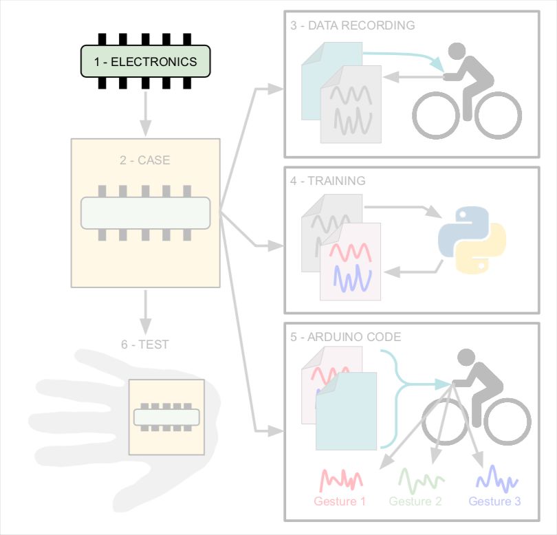
From steps 2 to 7, I provide the same diagram, indicating the steps on it so that it is easier for you to understand the process of making a glove.
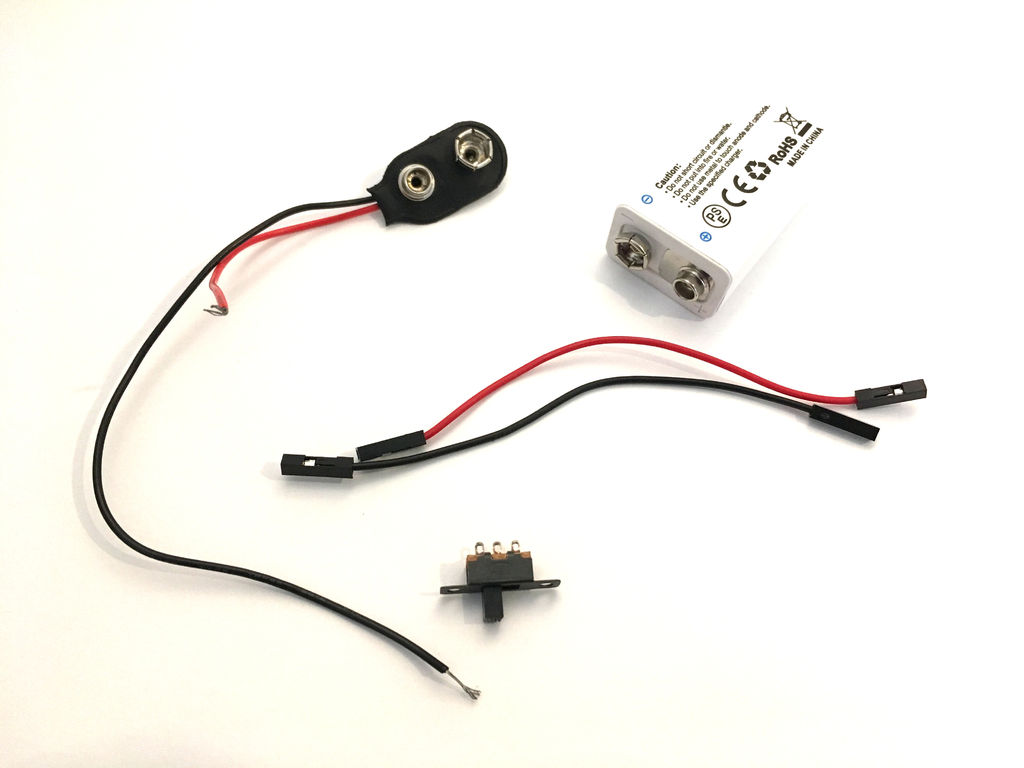
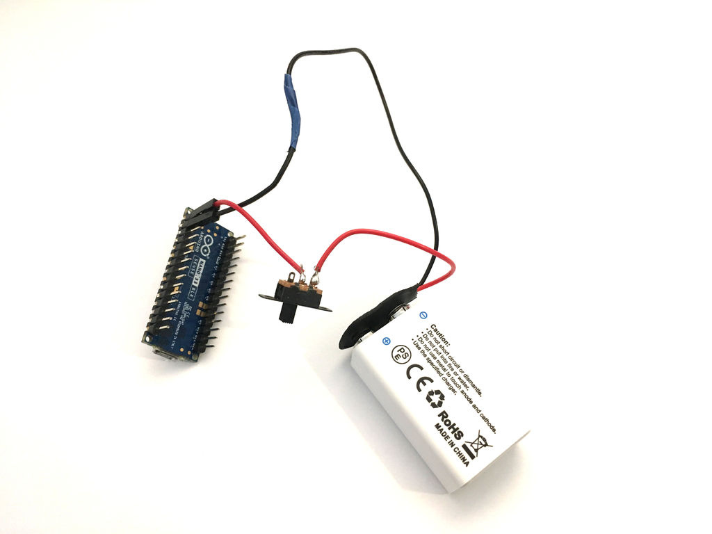
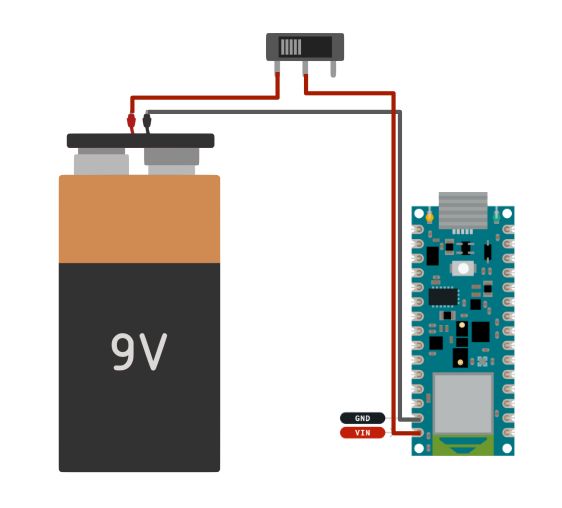
The electronics circuit for the glove is very simple:
- Arduino board.
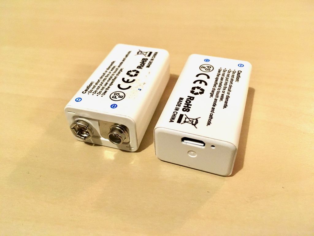
- 9V battery (I use a rechargeable battery).
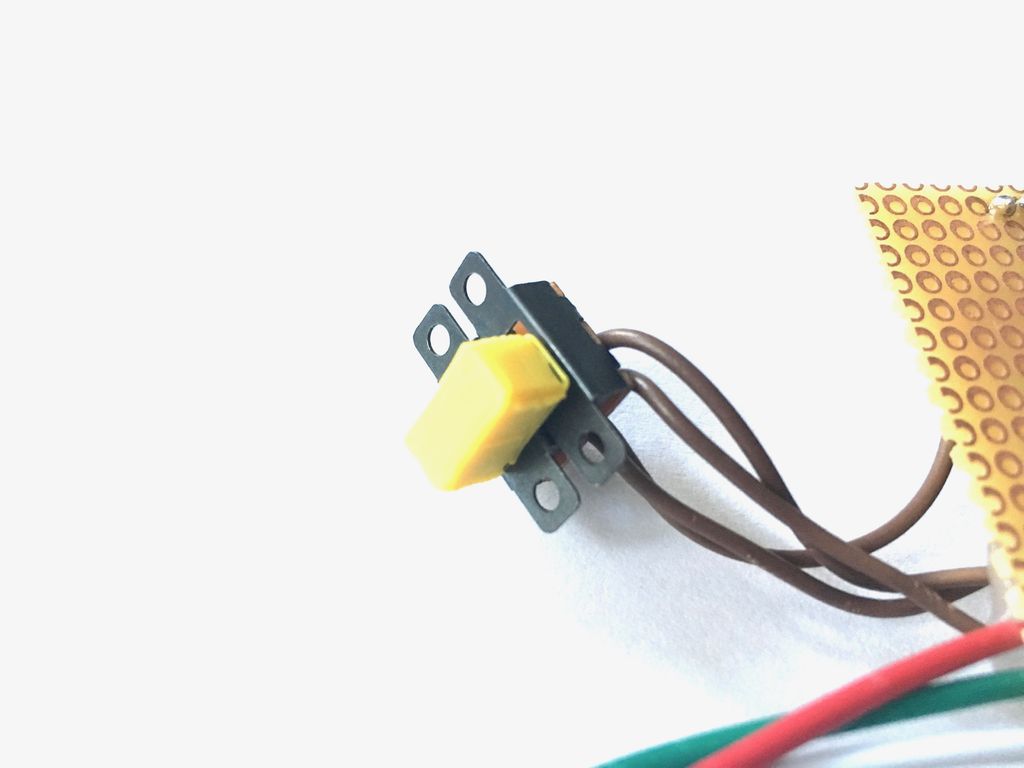
- SPST switch.
Step 3: glove 2/6 - body


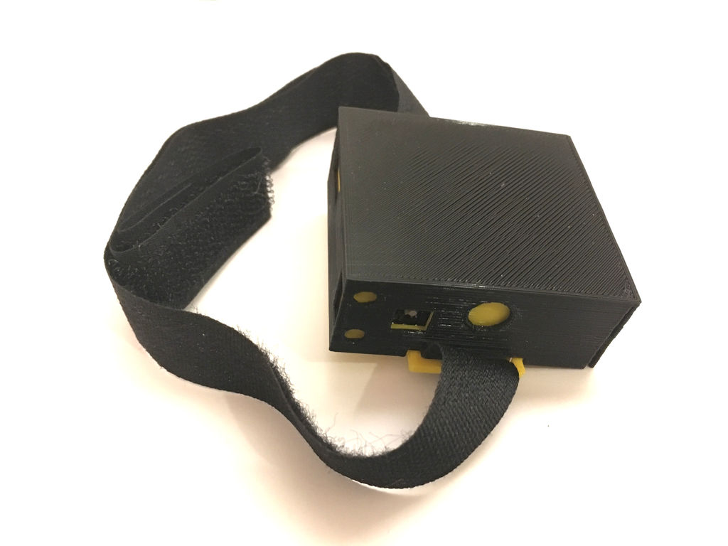
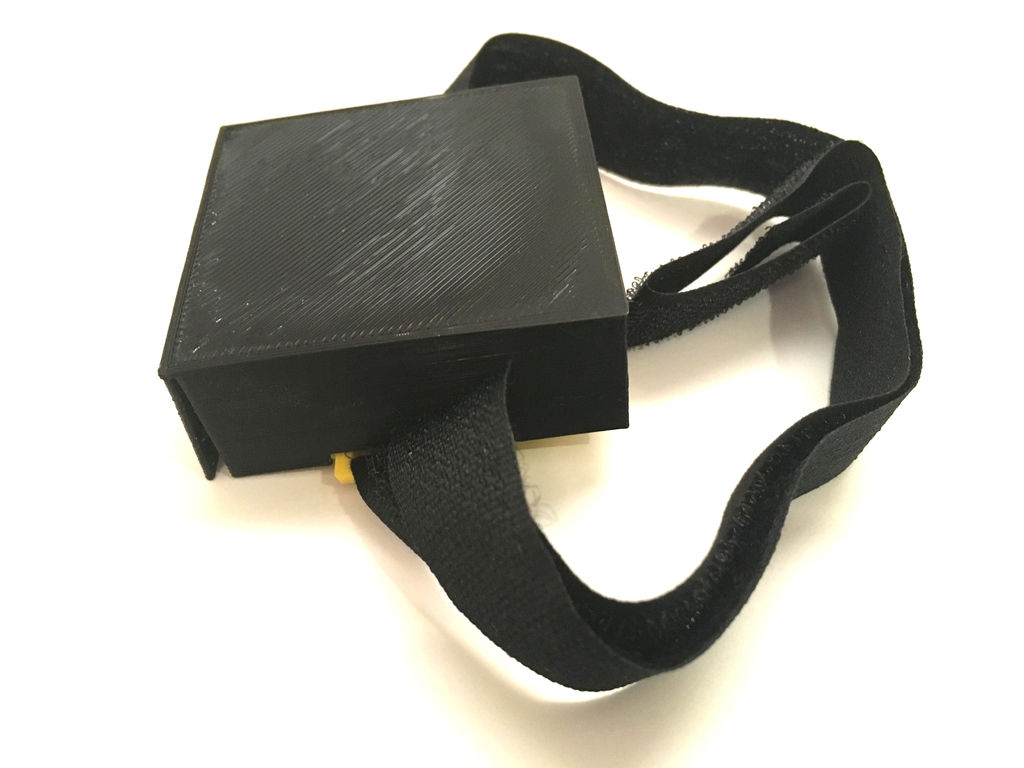

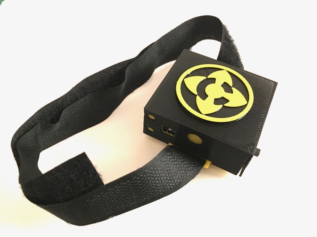
The case is simple, and consists of only two parts, printed on a 3D printer:
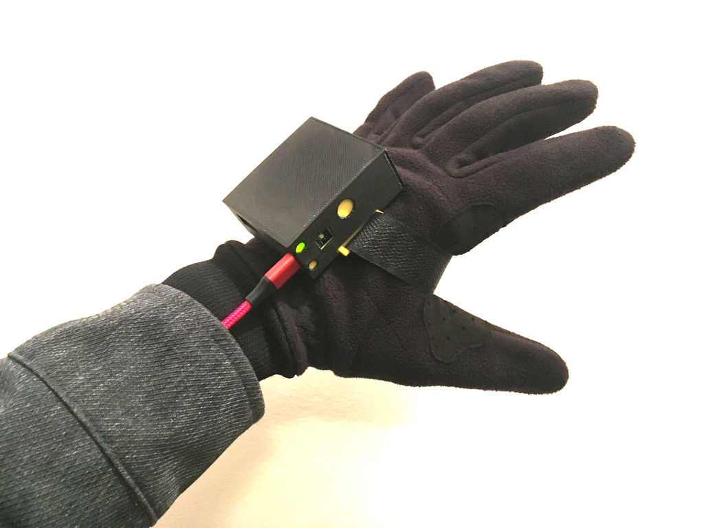
- The yellow part contains the Arduino board, battery and switch. Holes in the case allow you to recharge the battery and reprogram the Arduino board without having to disassemble the case.
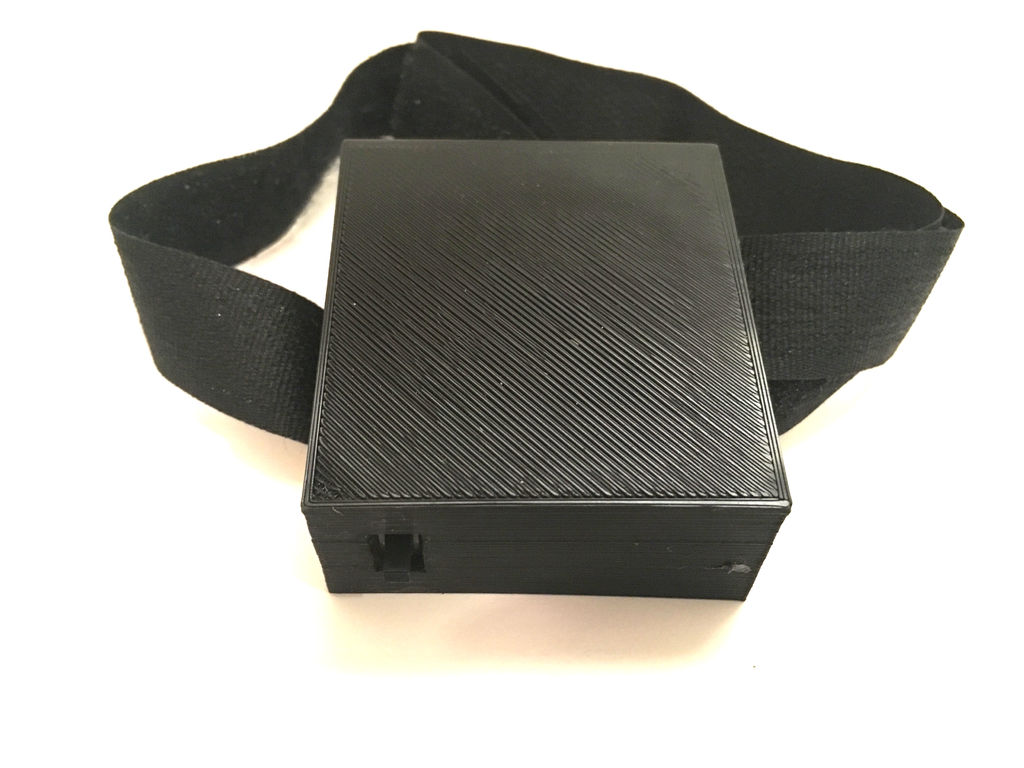
- The black part is the cover that protects the battery and the board.
I attach it to my hand with a strip of Velcro.
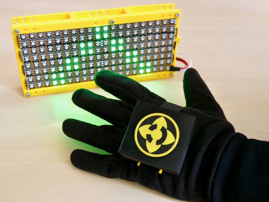
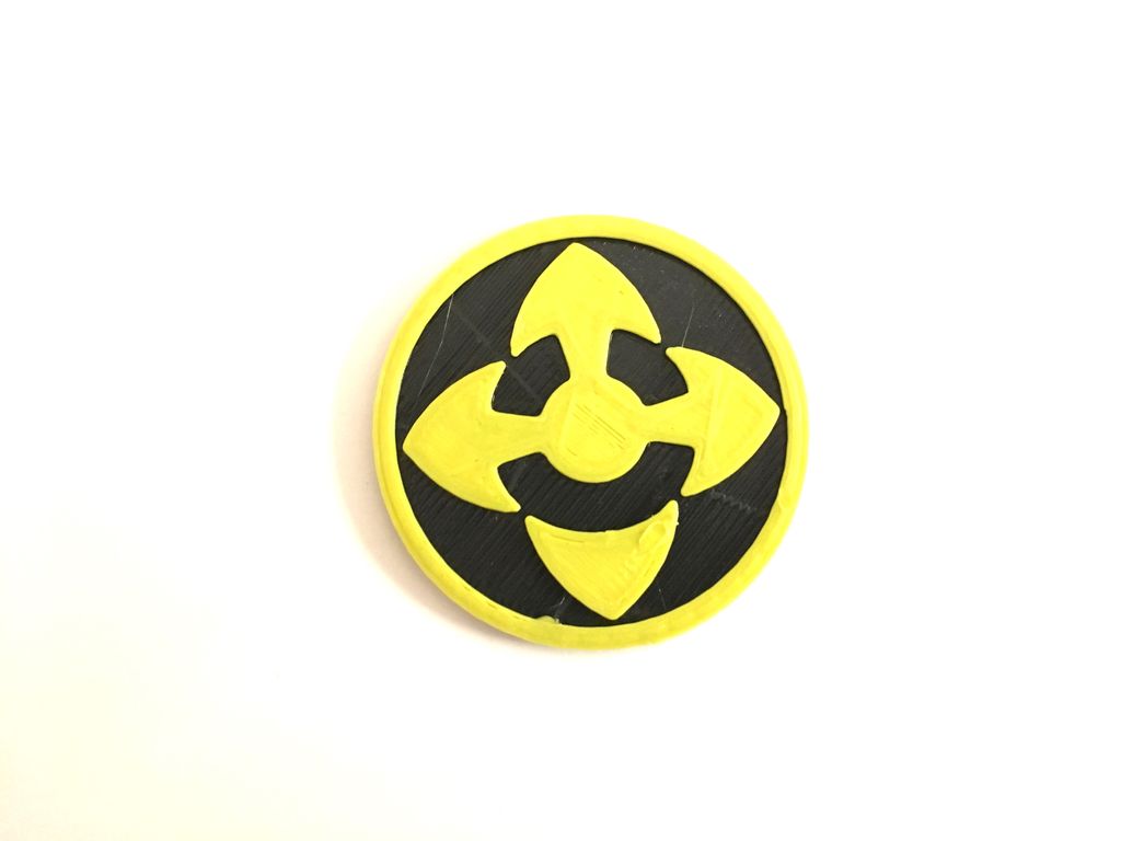
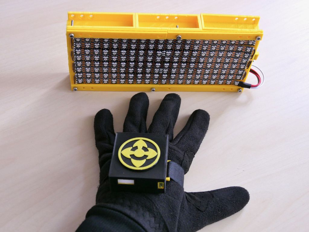
I also drew a logo, which I then glued to the lid. It represents the cyclist being viewed from above and has three arrows - straight ahead, left and right. The fourth arrow is separated from the other three, because bicycles don't go backwards.
Files
content.instructables.com/ORIG/FS2/L3M3/K9N93ZYW/FS2L3M3K9N93ZYW.stl
content.instructables.com/ORIG/F72/21NG/K9N93ZZG/F7221NGK9N93ZZG.stl
content.instructables.com/NVNZ3FD3/K8K8 stl
Step 4: glove 3/6: data recording


After assembling the device, it's time to write data. The goal is to record each gesture multiple times. I set the threshold for the gyroscope, and when it goes beyond this value, the Arduino starts to output the recorded data to the monitor.
I recorded the following gestures:
- The hand points to the left (a standard cyclist gesture to turn left).
- Braking (gesture with fingers reaching for the brake lever).
- The hand leans back.
- The hand leans forward.
- The hand leans to the left.
- The hand leans to the right.
Naturally, you can record your gestures.
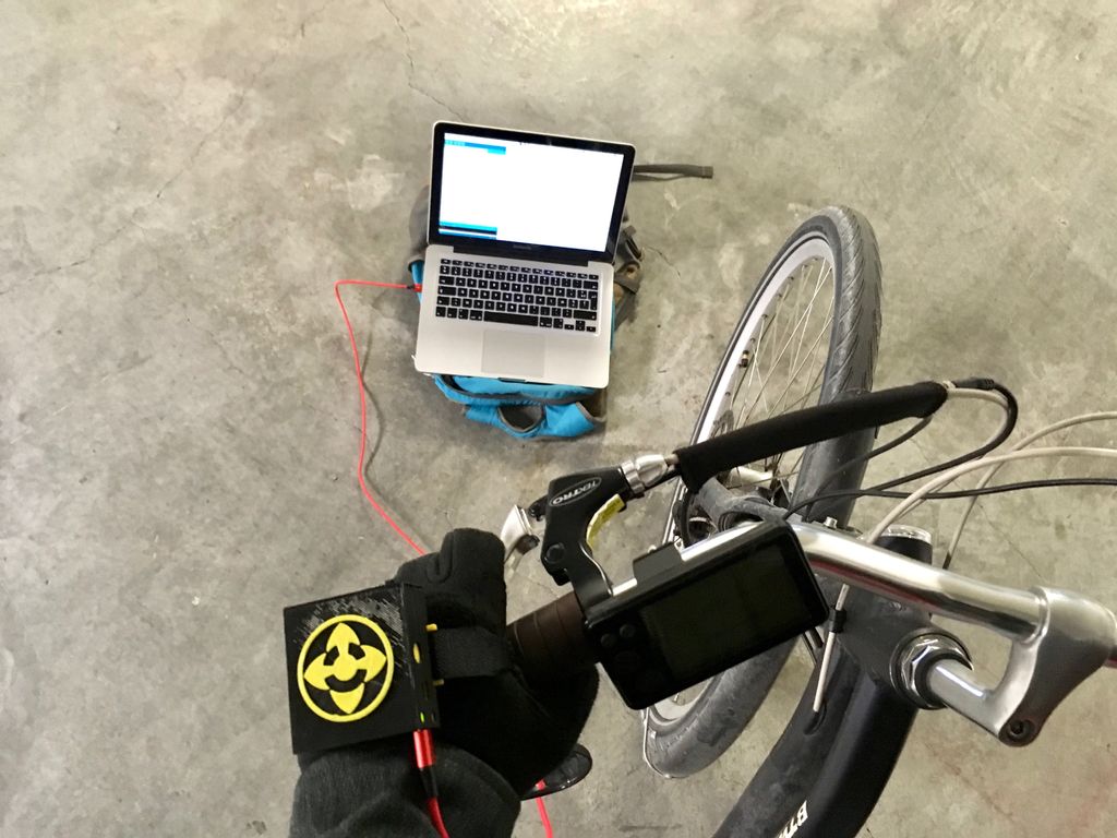
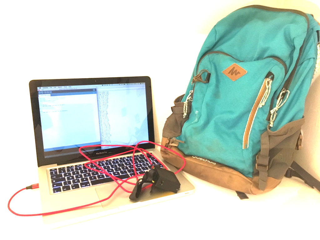
To record the data, I wrote a program that switches colors on the LED after every 20 strokes. It helped me understand when to move on to another gesture. I connected the Arduino to my computer, opened the port tracking program, and put the laptop in my backpack.
Having recorded all the gestures, I went on to the last stage - I copied the data output to the program and saved it in csv format.
content.instructables.com/ORIG/FC7/B0JT/K9UEA78V/FC7B0JTK9UEA78V.ino
Step 5: glove 4/6: training
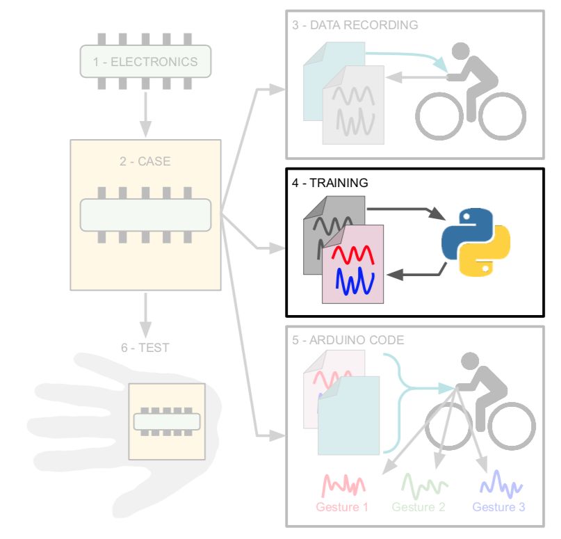

For training, I used the following example , correcting only a few lines in it. Before training, it is worth checking that for each gesture you have your own csv file, and the data in each file refers to this particular gesture.
On the Google Colab website, use the link in the "Upload data" section to upload your data.
In the "Graph Data (optional)" section, add the name of one of the files.
filename = "Arm_left.csv"
Then correct this line to only output the gyroscope data:
#index = range(1, len(df['aX']) + 1)
index = range(1, len(df['gX']) + 1)
Comment out the following lines - we do not use accelerometer data:
#plt.plot(index, df['aX'], 'g.', label='x', linestyle='solid', marker=',')
#plt.plot(index, df['aY'], 'b.', label='y', linestyle='solid', marker=',')
#plt.plot(index, df['aZ'], 'r.', label='z', linestyle='solid', marker=',')
#plt.title("Acceleration")
#plt.xlabel("Sample #")
#plt.ylabel("Acceleration (G)")
#plt.legend()
#plt.show()
In the "Parse and prepare the data" section, add all the file names:
#GESTURES = ["punch", "flex",]
GESTURES = ["Arm_left", "Brake", "Hand_back-tilt", "Hand_front-tilt", "Hand_left-tilt", "Hand_right-tilt"]
Change the number of samples by one gesture if you changed them in the Arduino code:
#SAMPLES_PER_GESTURE = 119
SAMPLES_PER_GESTURE = 64
It remains only to comment out the acceleration:
# normalize the input data, between 0 to 1:
# - acceleration is between: -4 to +4
# - gyroscope is between: -2000 to +2000
      tensor += [
          #(df['aX'][index] + 4) / 8,
          #(df['aY'][index] + 4) / 8,
          #(df['aZ'][index] + 4) / 8,
          (df['gX'][index] + 2000) / 4000,
          (df['gY'][index] + 2000) / 4000,
          (df['gZ'][index] + 2000) / 4000
      ]
After going through the entire program, you can download the trained model.
Files
content.instructables.com/ORIG/F7A/GLEK/K9UEA8Z5/F7AGLEKK9UEA8Z5.csv
content.instructables.com/ORIG/FV1/853G/K9UEA8Z6/FV1853GK9UEA8Z6.csv
content.instructables.com/ORIG8/FQKD9. csv
content.instructables.com/ORIG/F7N/P7AG/K9UEA8Z9/F7NP7AGK9UEA8Z9.csv
content.instructables.com/ORIG/FD4/WZRM/K9UEA8ZA/FD4WZRMK9UEA8ZA.csv
content.in7ea8struct2.com .csv
Step 6: Glove 5/6: Arduino
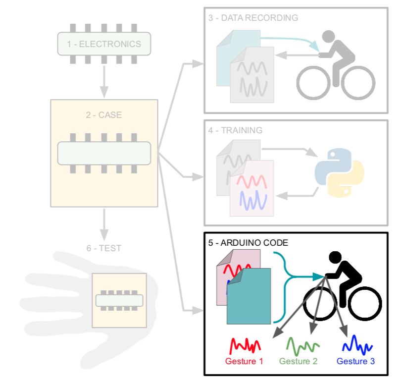
Code My final smart glove code is a mixture of the following programs:
- an example "LED" from the "ArduinoBLE" library (Peripheral> LED).
- "IMU_Classifier" from here .
I will not expand on them in detail here, I just recommend reading the original programs in order to better understand what is happening.
Add your model to the code and you can test it!
Files
content.instructables.com/ORIG/F9N/4SBK/K9UEA98M/F9N4SBKK9UEA98M.h
content.instructables.com/ORIG/FKZ/ODO9/KB52VXZK/FKZODO9KB52VXZK.ino
Step 7: glove 6/6: tests

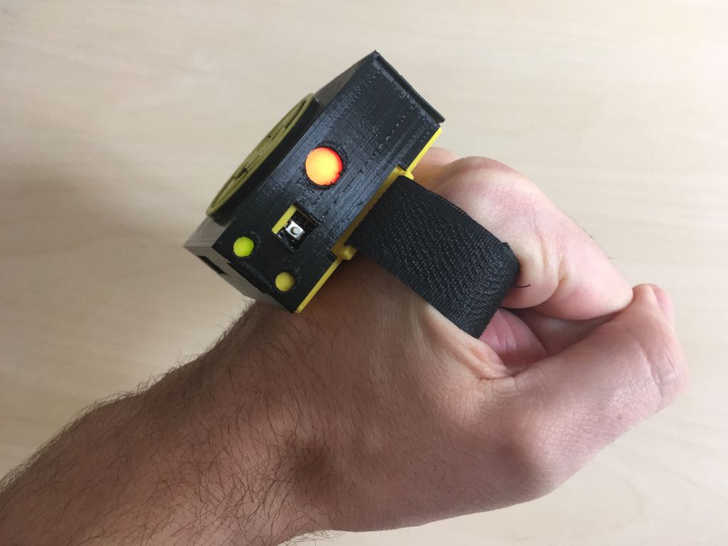

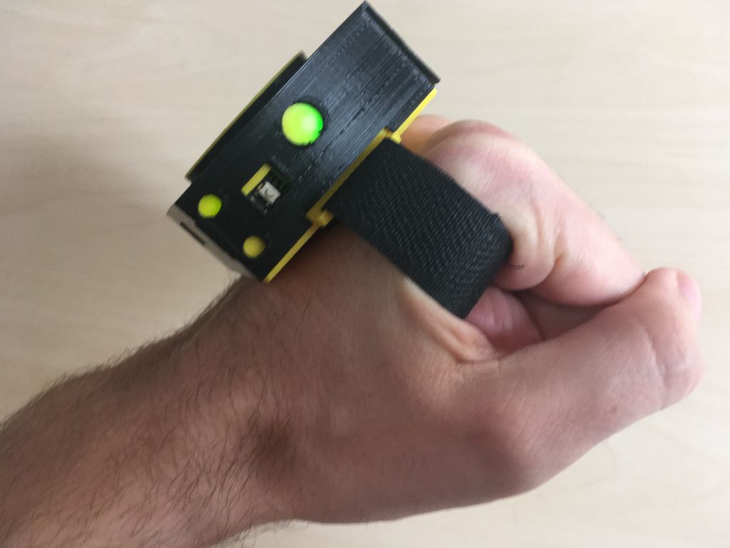
As you can see from the video, the LED lights up differently depending on the recognized gesture:
Step 8: 1/4 LED Matrix: Electronics


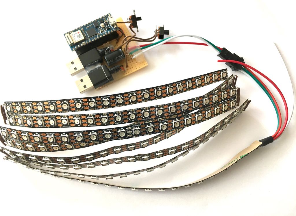
As I mentioned, when uploading a sketch from the ArduinoBLE library for an LED on the Arduino Nano 33 BLE SENSE, I ran into some problems. So I decided to use ESP32 instead of this board. Therefore, in the above photos you can see both boards.
Since both the Arduino Nano 33 BLE SENSE and ESP32 boards operate with 3.3V logic, I added a 4-level buffer from 3V to 5V (74AHCT125) as recommended in the instructions from Adafruit .
I also added a 100uF capacitor to protect the LED from sudden voltage surges.
I assembled the entire circuit on a breadboard.
It can be seen that I used both connectors of the external power supply, because I was afraid that the LED matrix would require too much current. Therefore, the matrix and the MI are powered from different connectors of an external power source.
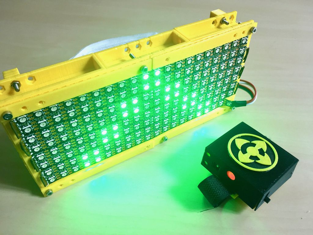
Step 9: LED Array 2/4: Body

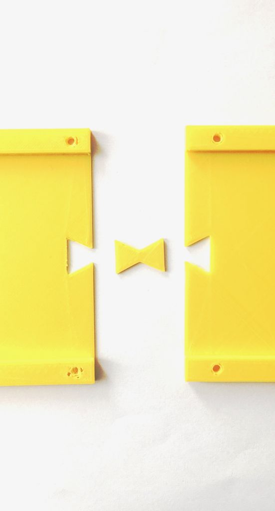

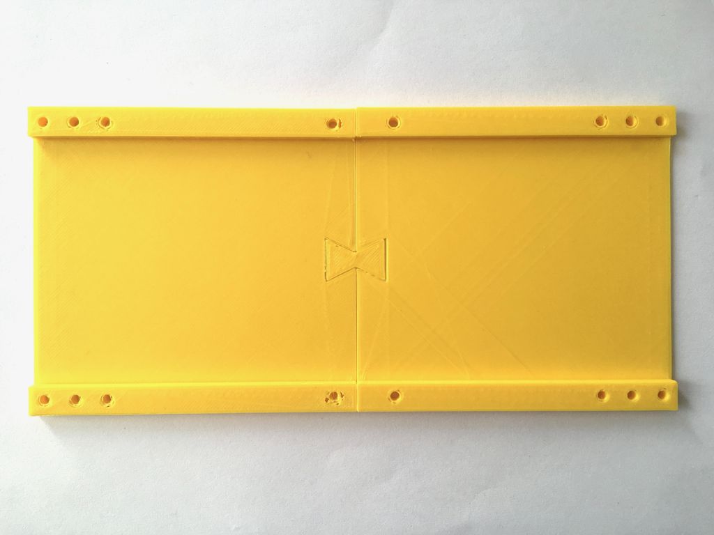

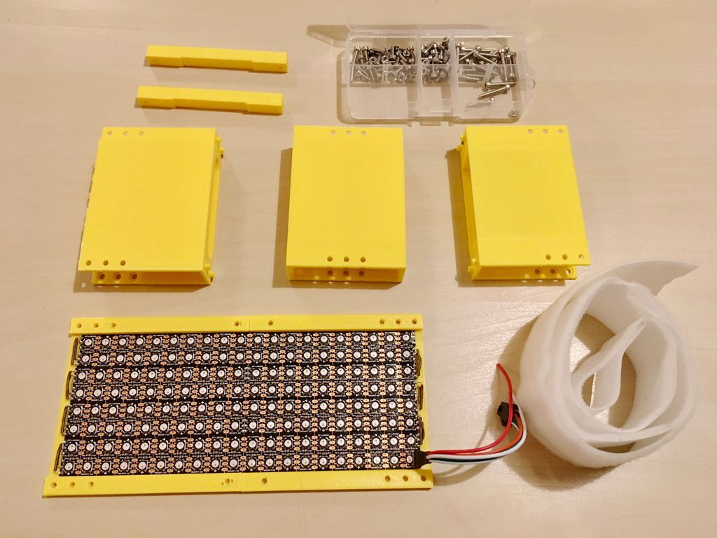


I needed a prefabricated LED matrix case. Therefore, it consists of several parts (and also because my 3D printer is very tiny), and I have provided holes for the bolts in them.
I used Velcro again to attach the panel.
Files
content.instructables.com/ORIG/FH6/TB4H/K9N93ZZJ/FH6TB4HK9N93ZZJ.stl content.instructables.com/ORIG/FK3/BZPC/K9N93ZZK/FK3BZPCK9N93ZZK.stl
content.instructFLUK9N93ZZK.stl
content.instructFLZZJ stl
content.instructables.com/ORIG/F38/BF1P/K9N93ZZM/F38BF1PK9N93ZZM.stl
content.instructables.com/ORIG/FJC/DQMY/K9N93ZZN/FJCDQMYK9N93ZZN.stl
contentNORIGVCT9FQ93/ .stl
content.instructables.com/ORIG/FJE/C5FG/K9N93ZZR/FJEC5FGK9N93ZZR.stl
content.instructables.com/ORIG/F55/1X43/K9N93ZZS/F551X43K9N93ZZS.stl
Step 10: 3/4 LED Matrix: Arduino Code


The resulting code is a mixture of the following codes (and their modification):
- BLE_Write example from BLE ESP32 ARDUINO library.
- MatrixGFXDemo64 example from FastLED NeoMatrix library.
I will not expand on them in detail here, I just recommend reading the original programs in order to better understand what is happening.
content.instructables.com/ORIG/FIR/RETZ/KB52VXP4/FIRRETZKB52VXP4.ino
Step 11: LED matrix 4/4: testing


It's time to check everything! After recognizing each gesture, a signal is sent to the LED matrix, and it shows a certain pattern. It can be seen that the LEDs on the glove light up according to the recognized gesture.
Step 12: final tests and conclusion
Here's how it looks live:
I am very pleased with the resulting device. Thanks to the project, I feel much more confident with tinyML and BLE. Since then, I bought another Arduino Nano 33 IOT, and now I am engaged in a very interesting project, which I will write about later. What would I change in the second version of the device I described:
- «». , . - - , . .
- . , USB . , . .
- . , . , ( 20 ). – , .
It took me several months to complete the project and write this text. If something is unclear, or some file is missing, write in the comments to the original article .
See also: