Author: Sergey Timofeev, programmer-developer of Top Systems CJSC.
Leader: Igor Batyuchenko, head of the development group of ZAO Top Systems.
The article describes the theoretical basis of new surface modeling operations in T-FLEX CAD 17, as well as their main purpose.
Products of complex shapes
Surface modeling is used in the design of a wide range of industrial products with complex shapes: from household appliances and cars to aircraft and marine vessels. One of the approaches to this type of modeling is to use a set of reference profiles and bypass curves, on the basis of which the transition surfaces are constructed.
However, often, using standard operations to create this kind of geometry is inconvenient and inefficient in terms of time spent. When solving problems of constructing surfaces with given characteristics, designers need to use a single tool that allows you to choose various options for specifying the initial data (for example, surfaces of a conical section). Therefore, we have created a mechanism for constructing this kind of surfaces with a common set of properties where it is permissible.
1. Transitional surfaces
In T-FLEX CAD 17, an operation that includes a family of surfaces with a conical section has a generic name "Transition surface". Purpose of the operation: to create a transition surface between two other surfaces (for the most part), but having certain boundary conditions, as well as a specific, although possibly variable in "length", cross-sectional shape (more on this later).
Currently, the operation has in its arsenal ten construction methods, divided into three groups according to the type of section:
conical, 4 types;
circle (arc), 4 types;
straight, 2 types.
. , . , «» ( ).
, ( ): , ( ), . , . . , , , , () ?
«?»: « » — , , , , . . :
— () , , – (. 1 – ).
— «» (. 1).
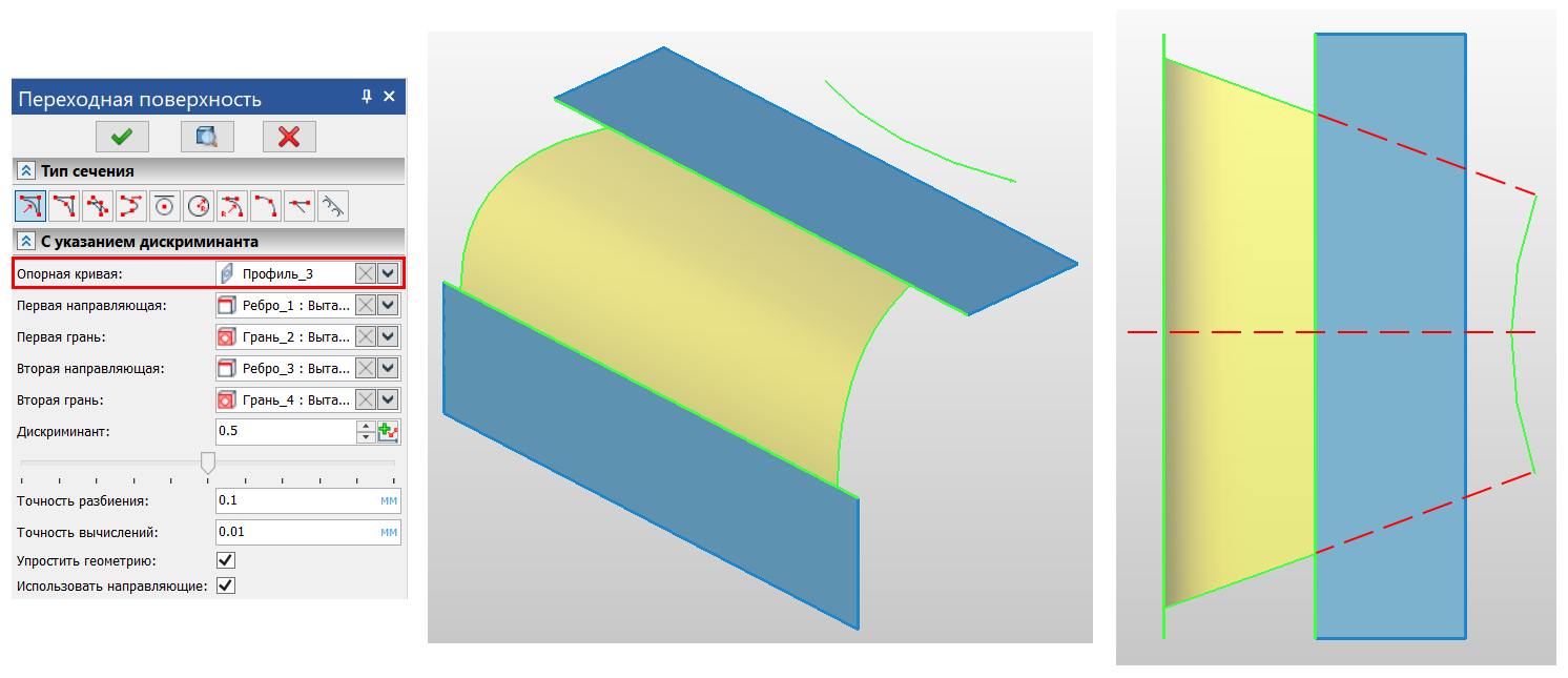
1.
, «» ( ) , . , ( ). — :
— «» — (0; 1). 2 (. 2 – , ). (0; 0.5) — ; 0.5 – ; (0.5; 1) – . , 0.4142 ( ) — .
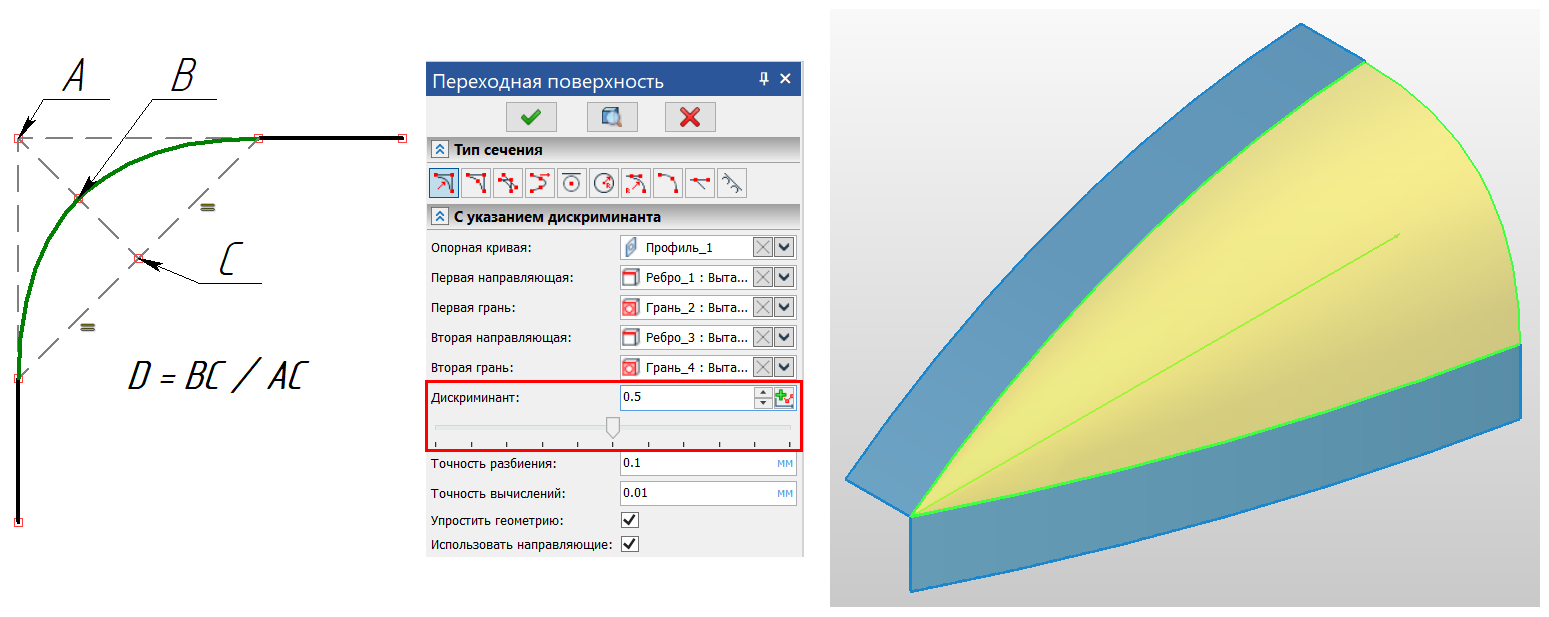
2. ,
( – ; – )
— « » — , . , , 3 (. 3, ABC).
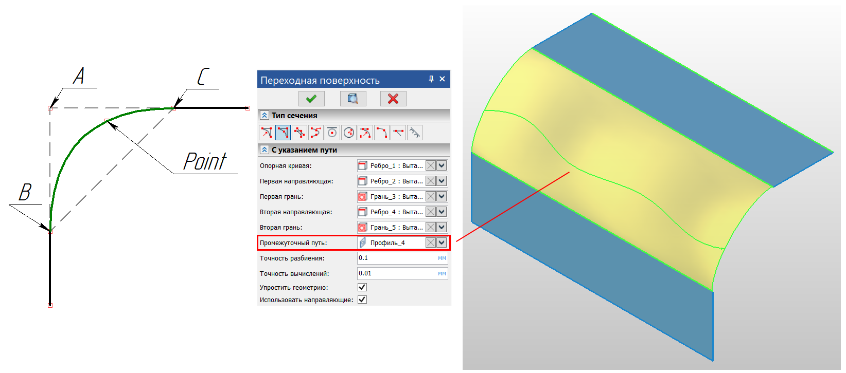
3. (Point – )
, (), . : «» — ; « » — ; « 3D » — , .
, (, « »), , – (. 4).
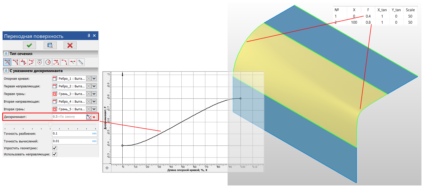
4. , (0.4; 0.8)
, . – . «» .
2.
– , . , . , «» (, ..), . :
— – ;
— (. 5).
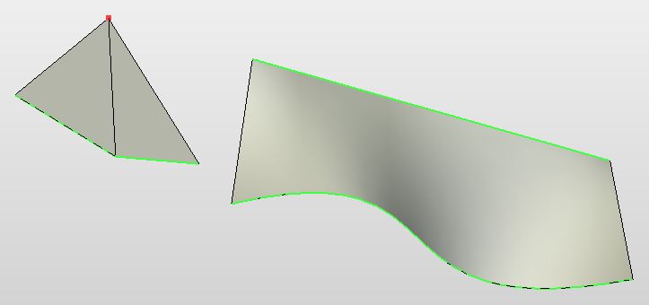
5. ( — )
«» , . – , . ? . – . . , , « » ( ).
« » T-FLEX CAD 17. ( ) . , .
, , : «» . , , ( ), , : « ?». , .
, , . « » « » . , , . «», () UV . .
— :
. 6 (. 6).

6. ( – )
— :
. « ». (. 7).

7.
, , , , (. 8). ( ).

8. « » « »
3.
: , ( ). , « » , – , .
:
—
— ( – ). ? , «» . , , . «». (. 9).

9. «»
: «G1» ( ) «G2» ( — ). . «G2» . , , ( ). , (. 10).
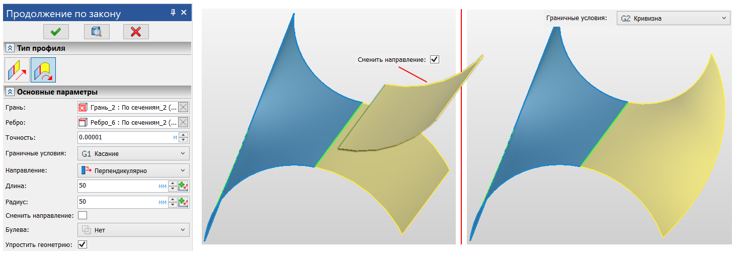
10. «» «G1» «G2»
, .
—
. , , , «». ( ). . «»: , (. 11).

11.
– ( ). , , « » ( ), . , .
, , ( ), , . , (. 12), , , «» .

12.
:
- : «» «» . , « ».
- : , , «» (. 13, ).
- : ( ) . «», (. 13, ).
- : , . «» , . «» — , «» «» (. 13, ).
- : . «».

13. ,
, ( 14).
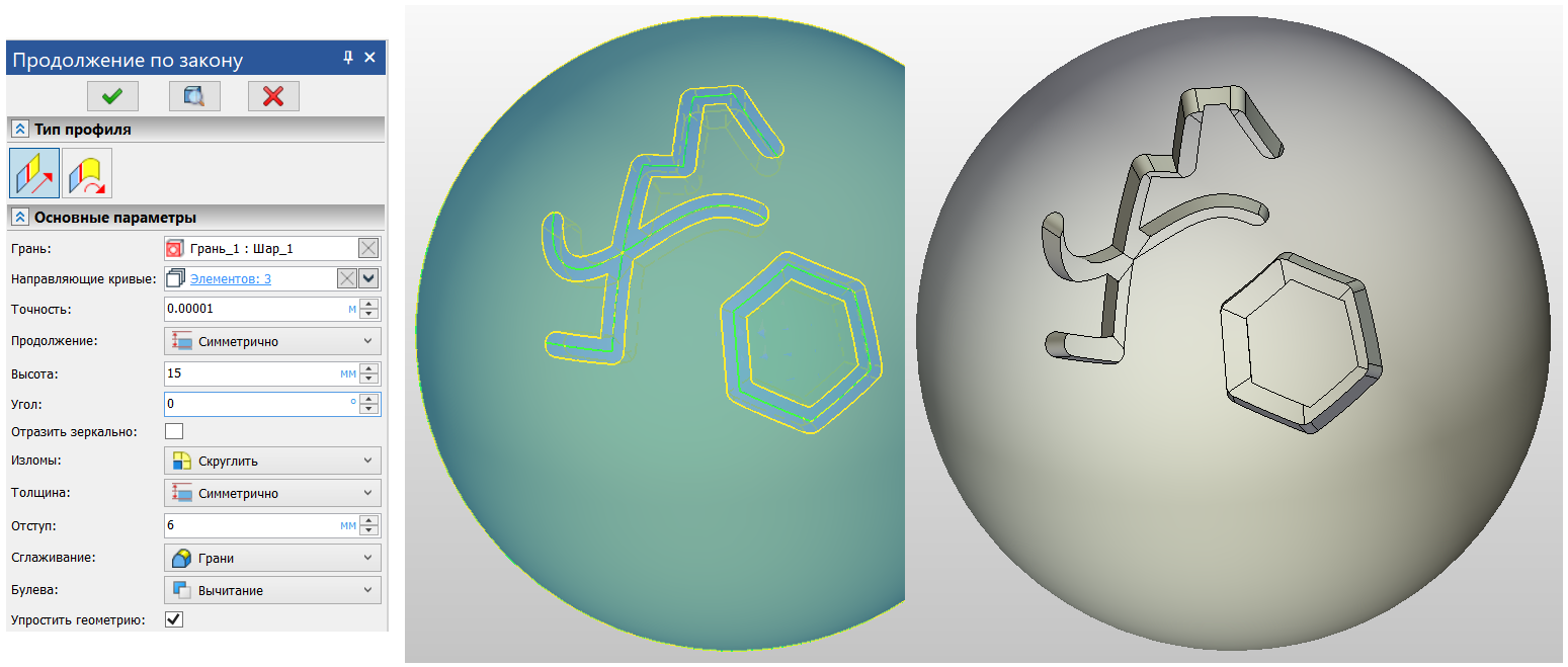
14. « »
It takes less than a second to recalculate this example on a modern PC. Nevertheless, the geometric operations involved in this example are rather "expensive" in terms of the resources used (due to the versatility of the operation). Nevertheless, such an operation is unique in its kind.
Conclusion
As mentioned at the beginning of this article, the surface modeling approach is used in many industries. Using basic CAD tools T-FLEX CAD, as well as the operations described above, you can design models of any complexity that meet all the requirements for the shape of the product, its ergonomics and aesthetics.