
For those who entered the thread for the first time, please read the previous issue .
Motor housing
Based on the data obtained on the pressure of gases in the combustion chamber, it was necessary to select a material for the body that meets these requirements. Our peak pressure reaches almost 25 bar. Without further ado and trying to avoid the use of complex materials, where possible, we decided to adopt a steel pipe DU-40 with a wall thickness of 3 mm. The corresponding pipe was successfully purchased from the first rolled metal product on the market. Unfortunately, the warehouse of iron products was in the open air, so the pipe was somewhat rusty.
Cleaning with sandpaper and a "petal stick" by Lyosha (we say hello to Dr. Dew) did not give a normal effect, and it was too lazy to kill for this time. Why not try the chemical method for this. Of the chemicals that were within walking distance, there were only vinegar essence, citric acid and salt, all purchased at the nearest grocery store. As luck would have it, there was no suitable basin in which to pour the vigorous mixture and soak the pipe, it was necessary to build it by the dendrofecal method from other boxes, using them as a support, and between them to make a bath from the film left after the airship, which was secured with clerical clips. We put a pipe in this crunchy sarcophagus and poured it with acetic acid, and for greater effect we added lemon with salt dissolved in water. The reaction began instantly. Satisfied with ourselves, we left the pipe to poison and left with a clear conscience for the weekend.
The smell that greeted us on Monday was eating away our eyes and nose. Yes, they didn't cover the bath with anything. The scent of vinegar seemed to have permeated the walls. Even the wide open windows did not help, then we had to ventilate the studio for another two days, so do not repeat our mistakes: it is better to do such things either outdoors or in a tightly closed container. Nevertheless, the result of cleaning the pipe was quite satisfactory: the pipe was cleaned both outside and inside. Keep in mind that after applying chemical cleaning, you need to rinse well with water and wipe dry the object to be cleaned, otherwise it will quickly become covered with a cloudy film in the air. Better yet, protect the surface from contact with air with paint, varnish or spray polyurethane. But these are exclusively our aesthetic considerations.
Calculation of the nozzle
The nozzle is the main element of the rocket engine (your K.O.), since depending on the correctness of its calculation, you can get up to + 30% thrust on the same fuel with the same channel.
We approached the calculation of the nozzle thoroughly, in detail about the mathematics of its calculation, the principle of operation, the processes occurring, and indeed, a lot of interesting things, you can read here and elib.osu.ru/bitstream/123456789/8572/1/1805_20110824.pdf . We also found a very convenient Rocki-nozzle tool on the site (we scroll down on the page and look for the corresponding link).
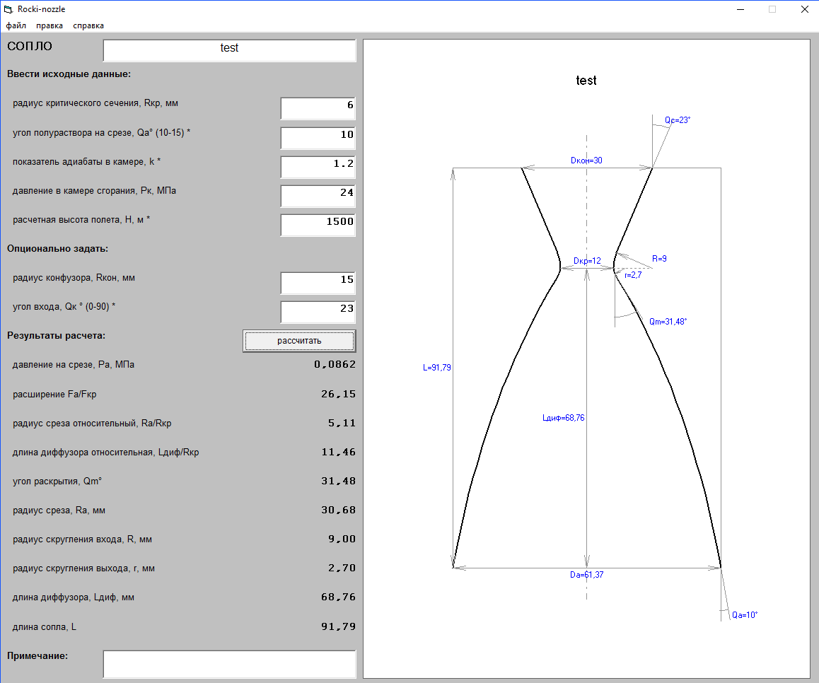
Download the program, substitute the calculated values of the rocket obtained in Meteor into the appropriate fields (see article) and get the nozzle profile at the outlet. We process the data and draw a beautiful nozzle in SolidWorks, respecting all dimensions.
Further there should have been a turner, but it will not get into this issue, since the CNC-shka refused to work for my friend, the turner and we could not get to him. But for the next episode, everything will definitely be.
You can download the resulting model using the link at the end of the article.
Test bench, mechanical part
Before launching the rocket, we wanted to measure the thrust at the test bench in order to compare the real diagrams with those calculated by Meteor and check how much we can trust its calculations. In principle, the question of the stand had been raised for a long time and its solution was inevitable, and, as usual, by trial and error.
The first version was the use as a sensitive element of a 10 kg kitchen scale with a potentiometer attached to the arrow axis. The scales were successfully purchased from an online store and disassembled for ease of use. But by this time, thrust calculations appeared and the understanding that the measurement range of 10 kg would be small, and I did not want to introduce an error in the form of levers.
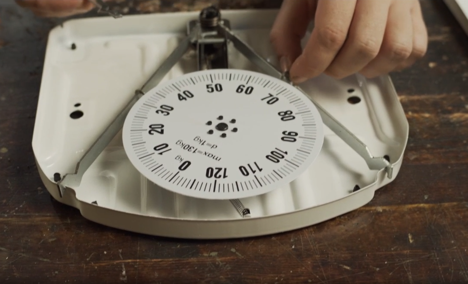
Then came option 2: use an analog (rotating disc) floor scale for people. When disassembled, inside there was a dead spring and a system of levers, extremely unsuitable for use on the stand.

Option 3. I did not want to use it for a long time because of the low measurement speed, however, I had to. Load cells. After scraping around the bottom of the barrel, I found several 50 kg strain gauges and a module on the HX711 chip at home.
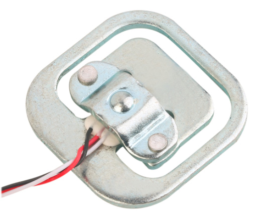

The main problem is that the strain gauges turned out to be not bridge, but half-bridge. Well, you have to put 2 pieces. On the other hand, this is even a plus: we will get a stand capable of measuring thrust up to 100 kg, and the resolution of the ADC in the HX711 24bit will allow us to measure with a fairly high accuracy. At least according to our calculations. How it will actually be, we will check the most accurate method - empirical.
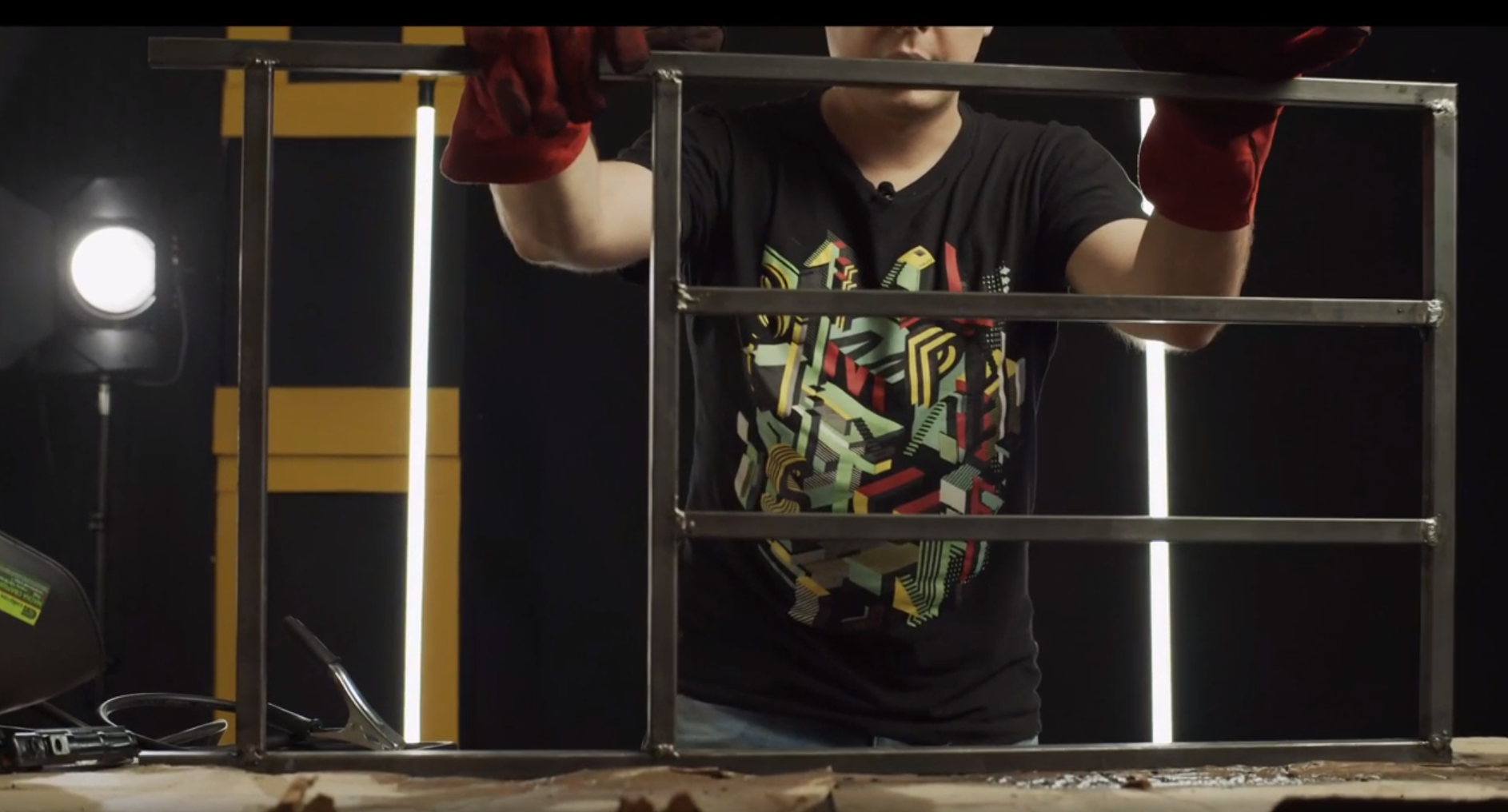
Meanwhile, Lyosha assembled the frame of the stand from a 20x20 shaped tube, steel guides and linear bearings. At first we thought that it was possible to put the engine under test in such a way that its thrust vector was directed downwards, that is, into the ground, but they abandoned this idea in favor of the accuracy of measurements, since at the start, the weight of the engine itself will press on the sensor, which will decrease as the fuel burns out. Instead, it was decided to direct the thrust vector parallel to the ground, and we will protect the stand from moving forward by fixing it with reinforcement or anchors driven into the ground. Well, or press it to the boulder - we'll look at the test site.


In the next series, we plan to completely assemble the stand, screw the electronics to it, assemble the engine, equip it with fuel, put it on the stand and go to deserted places for conducting fire tests. Stay with us - there will be many interesting things.
The video in the article can be viewed here:
Links:
How the Laval nozzle works
Calculating and constructing the profile of the Laval nozzle
Rocki-nozzle Software
Model of our nozzle