This is my little article describing (almost) everything I know about the Apple Lightning interface and related technologies: Tristar, Hydra, HiFive, SDQ, IDBUS, etc. But first, a little warning ...
Read this article at your own risk! The information is based on a lot of internal Apple Internal materials (data leaks, schematics, source codes) that I read diagonally. And, of course, on my own research. I must warn you that I have never done such research before. Therefore, this article may be using incorrect or simply strange terms and be partially or completely incorrect!
Before we dive deeper, let's briefly understand the terms:
What is Lightning?
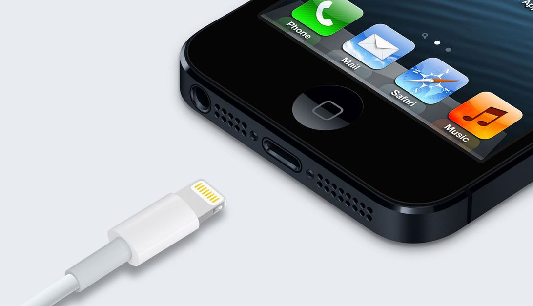
Lightning is the digital interface used in most Apple iOS devices since late 2012. It replaced the old 30-pin connector.
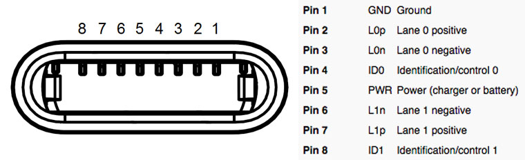
The picture above is the connector socket, and the picture below is its pinout:
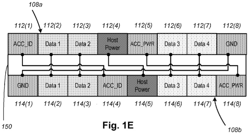
Please note that in the connector, the pins on both sides of the connector are not connected in the same order. Thus, the host device must determine the orientation of the cable before doing anything.
Although this is not always the case. Many Lightning accessories I've come across have mirrored pinouts in the connectors.
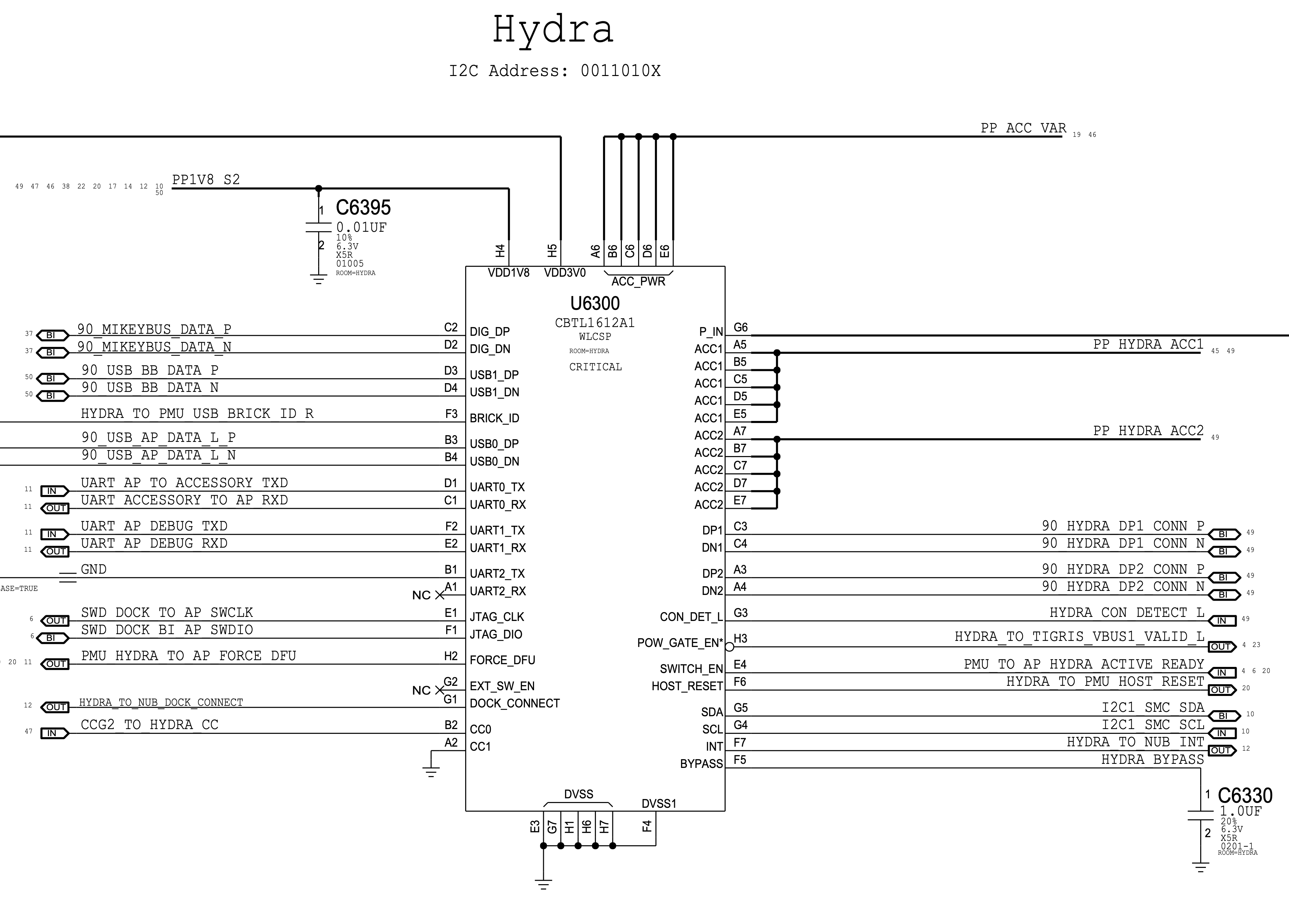
What are Tristar and Hydra?

Tristar is an integrated circuit built into every device with a Lightning connector. It is essentially a multiplexer:
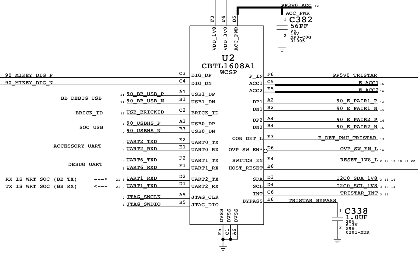
Among other things, its main purpose is to connect to the Lightning male connector as soon as it is plugged in - to determine the orientation, Accessory ID and properly route internal interfaces such as USB, UART and SWD.
Hydra is a new variant of Tristar, used since the iPhone 8 / X. Probably the most significant change is support for wireless charging, but this remains to be verified:
I am aware of five main variants of the Tristar / Hydra:
- TI THS7383 - First Generation Tristar in iPad mini 1 and iPad 4
- NXP CBTL1608A1 - First generation Tristar in iPhone 5 and iPod touch 5
- NXP CBTL1609A1 - mysterious first generation Tristar in iPod nano 7 - source
- NXP CBTL1610Ax - Second generation TriStar, used since iPhone 5C / 5S and apparently in everything else that does not support wireless charging. Several generations exist (x is the generation number)
- NXP CBTL1612Ax - Hydra is used with iPhone 8 / X and apparently everything else that supports wireless charging. Several generations exist (x is the generation number)
From now on I will only use the term TriStar, but keep in mind that it also stands for Hydra as they are very similar in most of the aspects that will be covered in this text.
What is HiFive?

HiFive is a child of Lightning, that is, a plug connector. It also contains a logic gate - this chip is known as SN2025 / BQ2025.
What are SDQ and IDBUS?
The two terms are often considered synonyms of sorts. For convenience, I will only use the term IDBUS, since it seems more correct to me (and this is what the technology is called in the THS7383 specification).
So, IDBUS is a digital protocol used for communication between Tristar and HiFive. Very similar to the Onewire protocol .
Now we can start
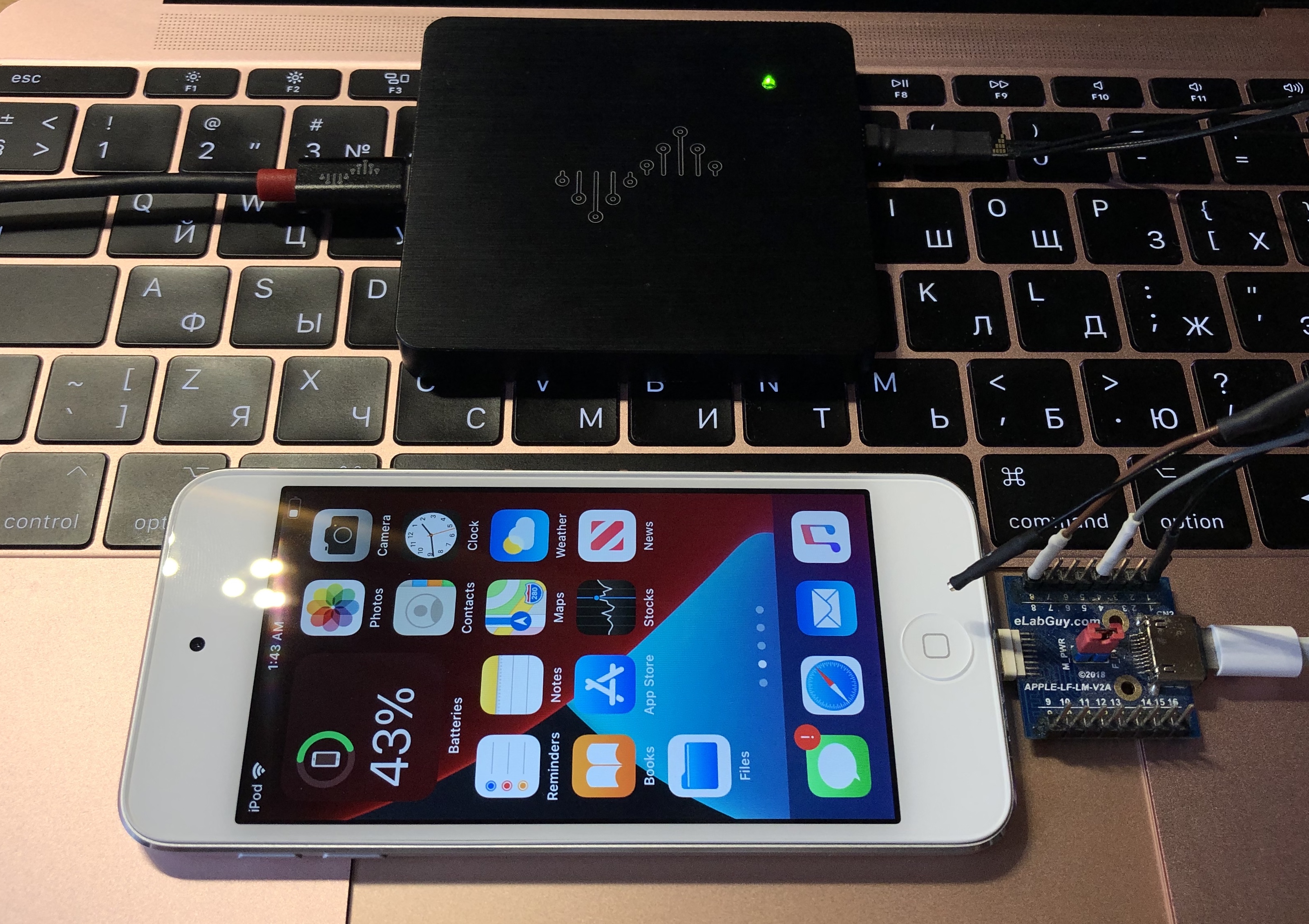
Let's listen to Tristar and HiFive communications. Get a logic analyzer, a Lightning riser with a jack and a male connector, an accessory (a regular Lightning-to-USB cable works great), and of course a device with a Lightning port.
First, connect the logic analyzer channels to both ID lines of the riser (pins 4 and 8) and connect the board to the device, but do not connect the accessory yet:

Immediately after that, start sampling (any frequency from 2 MHz or higher will do). You will see something like this:
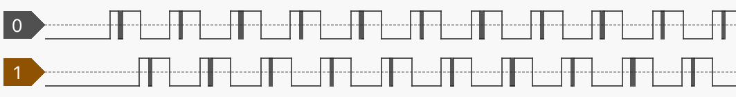
As you can see, Tristar polls each ID line in turn, one after the other. But since we didn't plug in any accessory, the survey clearly failed. At some point, the device will get tired of this endless stream of failures and stop it. For now, let's see what exactly happens during the poll:
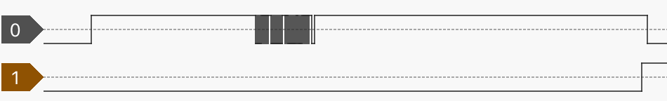
First, we see a long interval (about 1.1 milliseconds), when the level is just high, but nothing else happens:
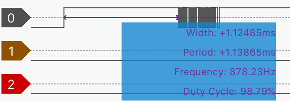
Apparently, this time is used to charge the internal HiFive capacitor - the energy from it will then be used to power the internal logic chips.
Much more interesting is what happens next:

Obviously, this is a stream of some data. But how to interpret it? How to decrypt? Let's virtually divide it into minimal significant parts - what I call words :

In fact, a word is a combination of falling-rising-falling:
- Content stage - the interval that determines the meaning of the word
- Recovery phase - the interval that is apparently required to process the content phase on the receiver's side and / or to prepare the next word at the sending phase
Here is a table of famous words with their spacing for both stages that we discussed above (all units in microseconds):
| Content | Recovery | ||||
|---|---|---|---|---|---|
| Word | Min | Typ | Max | Min | Typ |
| BREAK | 12 | fourteen | sixteen | 2.5 | 4.5 |
| WAKE | 22 | 24 | 27 | 1100? | |
| ZERO | 6 | 7 | 8 | 3 | |
| ONE | 1 | 1.7 | 2.5 | 8.5 | |
| ZERO and STOP * | 6 | 7 | 8 | sixteen | |
| ONE and STOP * | 1 | 1.7 | 2.5 | 21 | |
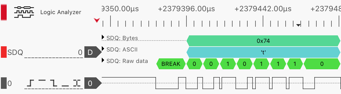
Using the table above we can now build a simple protocol decoder:
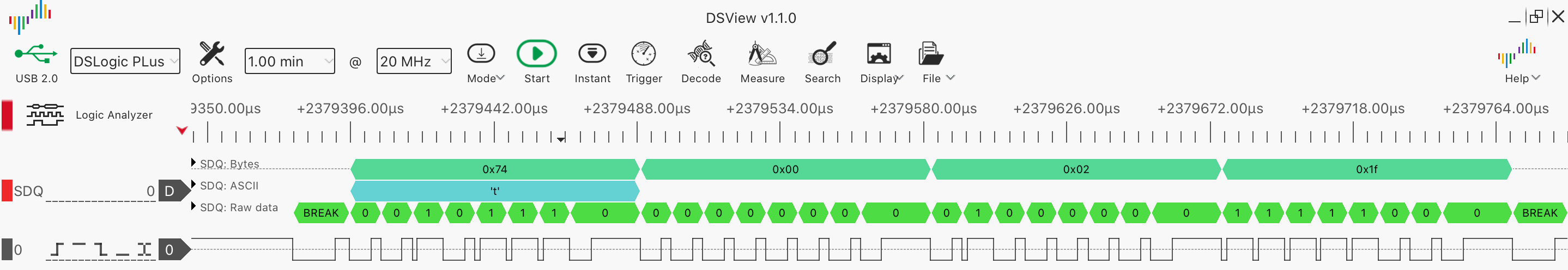
As you can see, the host sends a BREAK first - when Tristar wants to send a new request, the host always starts with that word. Then comes the data transfer stage. Please note that the last (8th) bit in a byte has a longer recovery phase. When the data transfer phase ends, the host sends another BREAK. The child must then send a response (after a delay of at least 2.5 microseconds - see table). Tristar will wait about 2.2ms for a response. If no response is given within this time frame, Tristar will try to interrogate another ID line.
Now let's look at the data stage using the example above -
0x74 0x00 0x02 0x1f:
0x74- type of request / response. Always even for a request and odd for a response (request type +1)
0x00 0x02- factual data. May be empty
0x1f- this is the CRC8 of both the request type byte and all data (polynomial - 0x31, initial value - 0xff)
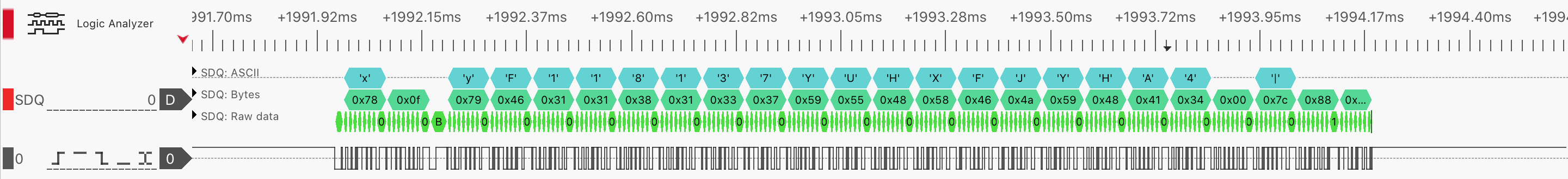
Let's connect some accessory to our rig and see what happens. I'll be using Apple's original Lightning-to-USB cable:
And here's what appears on IDBUS after the 0x74 request:
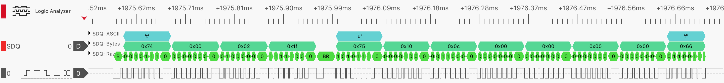
HiFive answered! And if you scroll further, you will see many other request / response pairs:
Some requests do not need a response:
Interpreting IDBUS Requests and Responses
The most important IDBUS request is 0x74, it is used for two purposes: to tell HiFive to turn on full voltage and amperage (if supported by the accessory), to ask it about the pin configuration that the cable supports, and some other metadata.
Not much is known about how the 0x75 response data is encoded. But some bits are available in the old Tristar spec:
First response data byte 0x75
| 7 | 6 | five | 4 | 3 | 2 | 1 | 0 |
|---|---|---|---|---|---|---|---|
| ACCx | Dx | DATA [43:40] | |||||
ACCx config when ID is found on ID0
| ACCx [1: 0] | ACC1 | ACC2 | HOST_RESET |
|---|---|---|---|
| 00 | Hi-Z (IDBUS) | Hi-Z | Hi-Z |
| 01 | UART1_RX | UART1_TX | Hi-Z |
| ten | JTAG_DIO | JTAG_CLK | Hi-Z |
| eleven | Hi-Z | Hi-Z | HIGH |
ACCx config when ID is found on ID1
| ACCx [1: 0] | ACC1 | ACC2 | HOST_RESET |
|---|---|---|---|
| 00 | Hi-Z | Hi-Z (IDBUS) | Hi-Z |
| 01 | UART1_RX | UART1_TX | Hi-Z |
| ten | JTAG_DIO | JTAG_CLK | Hi-Z |
| eleven | Hi-Z | Hi-Z | HIGH |
Dx config when ID is found on ID0
| Dx [1: 0] | DP1 | DN1 | DP2 | DN2 |
|---|---|---|---|---|
| 00 | Hi-Z | Hi-Z | Hi-Z | Hi-Z |
| 01 | USB0_DP | USB0_DN | Hi-Z | Hi-Z |
| ten | USB0_DP | USB0_DN | UART1_TX | UART1_RX |
| eleven | Hi-Z | Hi-Z | Hi-Z | Hi-Z |
Dx config when ID is found on ID1
| Dx [1: 0] | DP1 | DN1 | DP2 | DN2 |
|---|---|---|---|---|
| 00 | Hi-Z | Hi-Z | Hi-Z | Hi-Z |
| 01 | Hi-Z | Hi-Z | USB0_DP | USB0_DN |
| ten | USB0_DP | USB0_DN | UART1_TX | UART1_RX |
| eleven | Hi-Z | Hi-Z | Hi-Z | Hi-Z |
Using these tables, let's decipher the ID of our cable (
10 0C 00 00 00 00), taking into account the fact that the ID line is found on the ID0 pin:
The first byte of the 0x75 cable response
| 7 | 6 | five | 4 | 3 | 2 | 1 | 0 |
|---|---|---|---|---|---|---|---|
| ACCx | Dx | DATA [43:40] | |||||
| 0 | 0 | 0 | 1 | 0 | 0 | 0 | 0 |
So ACCx is 00, This means that the ID0 pin is simply tied to IDBUS, and Dx = 01 means that the DP1 / DN1 pins are configured as USB0_DP / USB0_DN. Exactly what we expected from a standard USB cable.
Now let's intercept something more interesting:
| Accessory | ID (HOSTID = 1) |
|---|---|
| DCSD | 20 00 00 00 00 00 |
| KongSWD (no Astris running) | 20 02 00 00 00 00 |
| KongSWD (with Astris running) | A0 00 00 00 00 00 |
| KanziSWD (no Astris running) | 20 0E 00 00 00 00 |
| KanziSWD (with Astris running) | A0 0C 00 00 00 00 |
| Haywire (HDMI) | 0B F0 00 00 00 00 |
| Charging UART | 20 00 10 00 00 00 |
| Lightning to 3.5mm / EarPods with Lightning | 04 F1 00 00 00 00 |
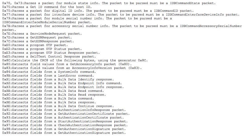
Here is a complete (?) List of IDBUS requests from @spbdimka :
Tip # 1 : You can easily get the properties of an accessory including its ID using accctl:
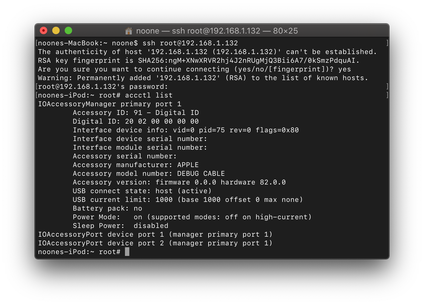
This is an internal Apple utility that comes with NonUI / InternalUI assemblies. But you can easily run it on any device after jailbreak.
Tip # 2 : You can easily get the pin configuration of a cable using diags:
tristar -p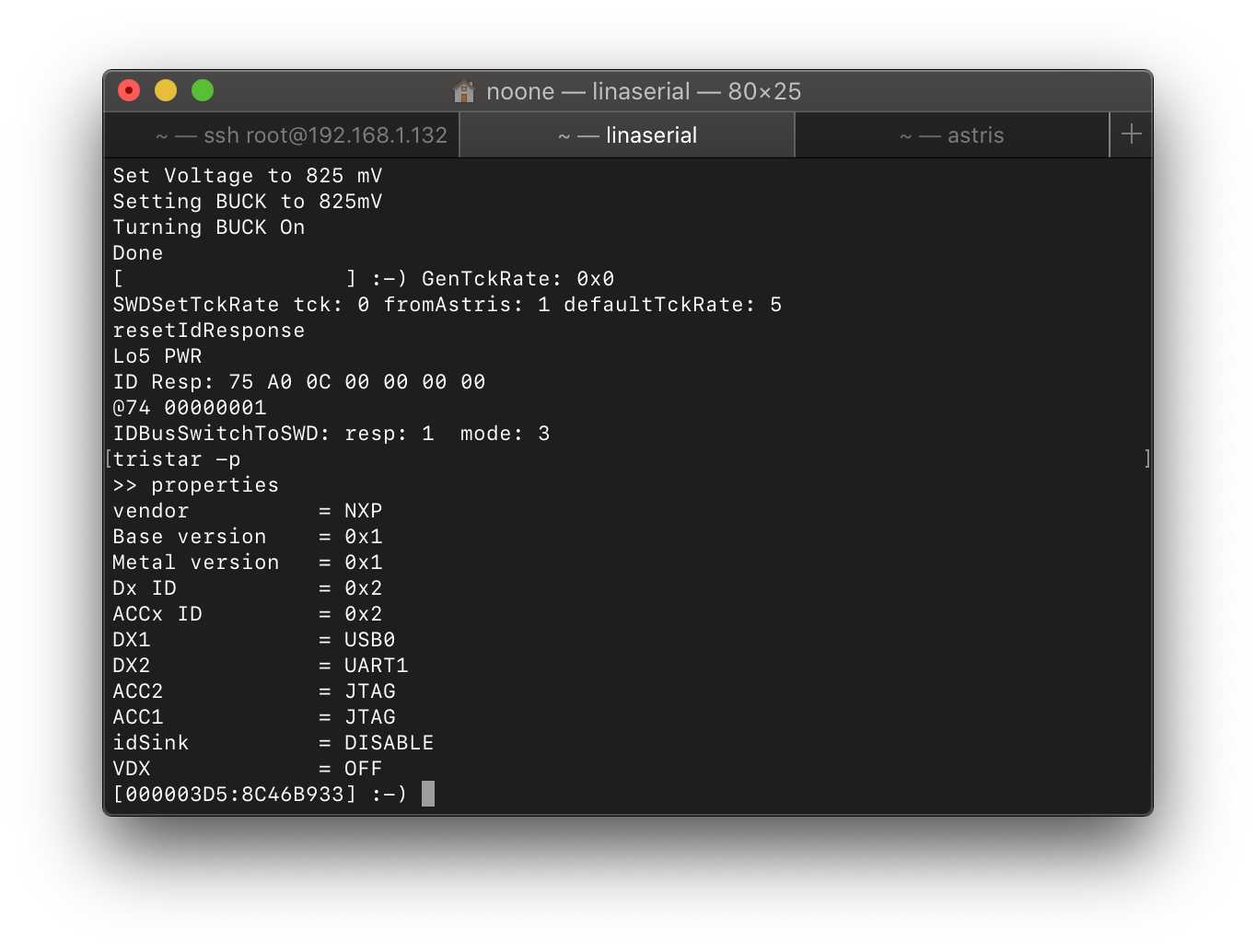
Please note that this command is only available on iOS 7+.
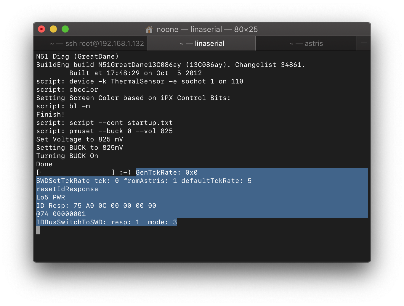
Tip # 3 : You can easily track 0x74 / 0x75 requests / responses generated by SWD probes by setting
debugenv var to 3:
astrisctl setenv debug 3Then on the virtual COM from the cable, you will see something like this:
HOSTID
In one of the tables above, you can see the mention of a certain HOSTID. This is the 16-bit value passed in the 0x74 request. It looks like it also affects HiFive's answer. At least if you set it to an invalid value (yes, it is possible with diags), HiFive stops working with it:
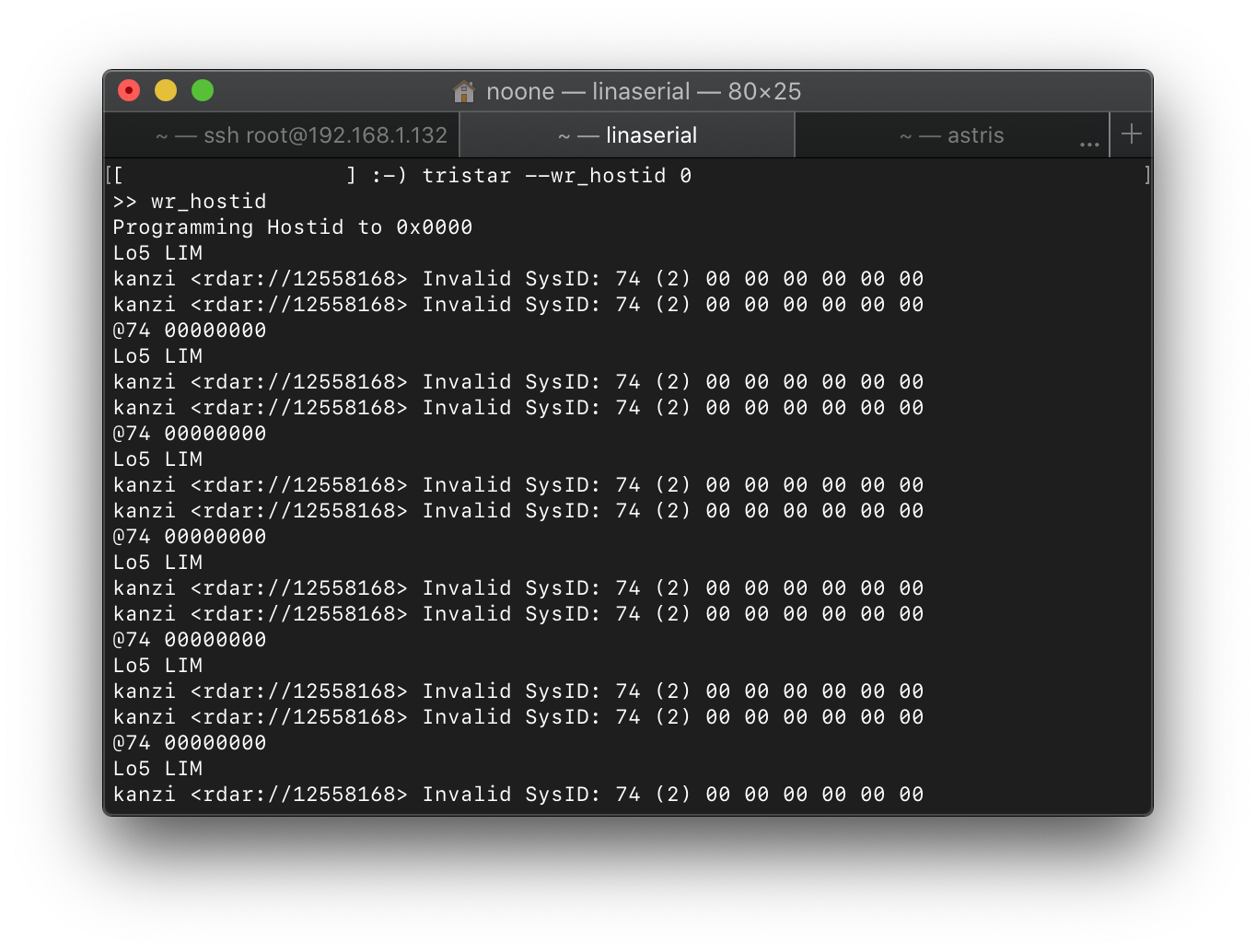
However, the KongSWD / KanziSWD firmware has an environment variable disableIdCheck, which you can configure to ignore the invalid HOSTID.
Important Note: Kong and Kanzi do not have HiFive as a dedicated non-programmable chip. These accessories emulate it with a microcontroller and / or FPGA, making it easy to update / reprogram.
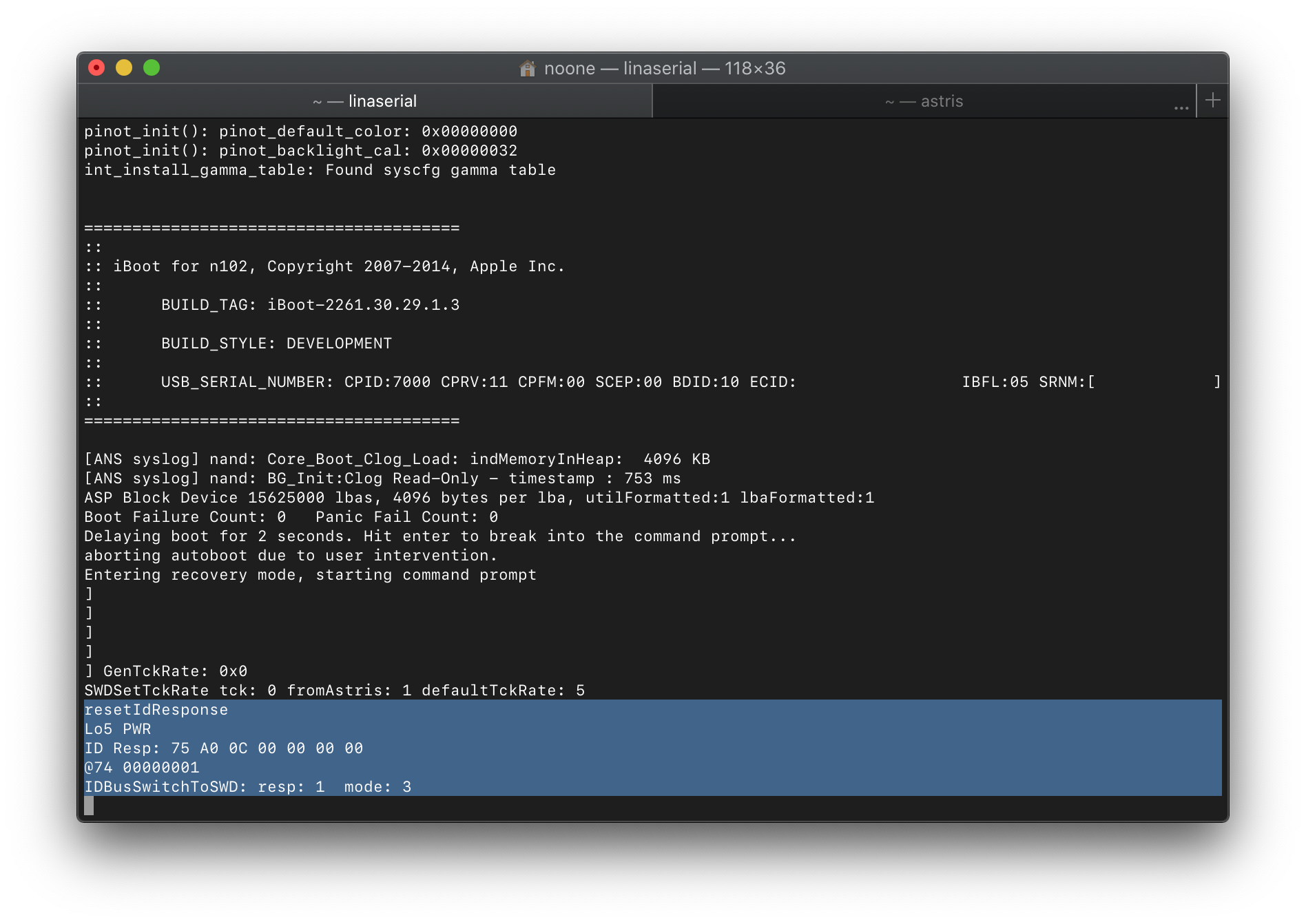
WAKE
In the Accessory ID table above, you can see that Kong and Kanzi send different responses depending on whether Astris is running or not, which is Apple's internal software for debugging with SWD probes (or probes). If you decipher these answers using the tables above, you will find that when Astris fails to start, the probe will act exactly like DCSD - USB on D1 lines and debug UART on D2 lines. But when the debug software is running, the ACCID lines switch to SWD.
But what if we want to launch Astris after the probe is already connected to the device? What will the cable do? How will it switch between ACC to SWD lines? This is where WAKE comes into play! HiFive (or a device that emulates it) can initiateWAKE - and the IDBUS enumeration process will start again: Tristar will send a request 0x74, Kong / Kanzi will respond with a new ID, Tristar will confirm it and send ACC lines to SWD extensions (SoC must support this at the physical level, of course).
Power handshake
The last thing I'm going to look at is the power handshakes. This is an IDBUS request / response algorithm that the Tristar kernel drivers use before allowing accessory charging.
When the Lightning cable just lies somewhere, connected to the charger / computer, but not connected to the device, HiFive limits the current on the PWR to a really small value (about 10-15 mA according to my measurements). To enable full current, request 0x74 must be issued by Tristar and processed by HiFive. For SecureROM / iBoot, this is sufficient, but additional steps must be taken when loading the kernel:
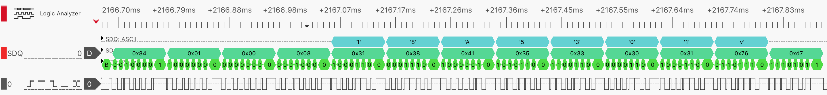
- TriStar issues two 0x70 requests
- As soon as the second request is processed by HiFive and a response is sent, it turns off the current altogether for about 20 milliseconds
- Tristar 0x70, 0x80 . HiFive
- , Tristar,
: , . , . ,
ESN Tristar I2C
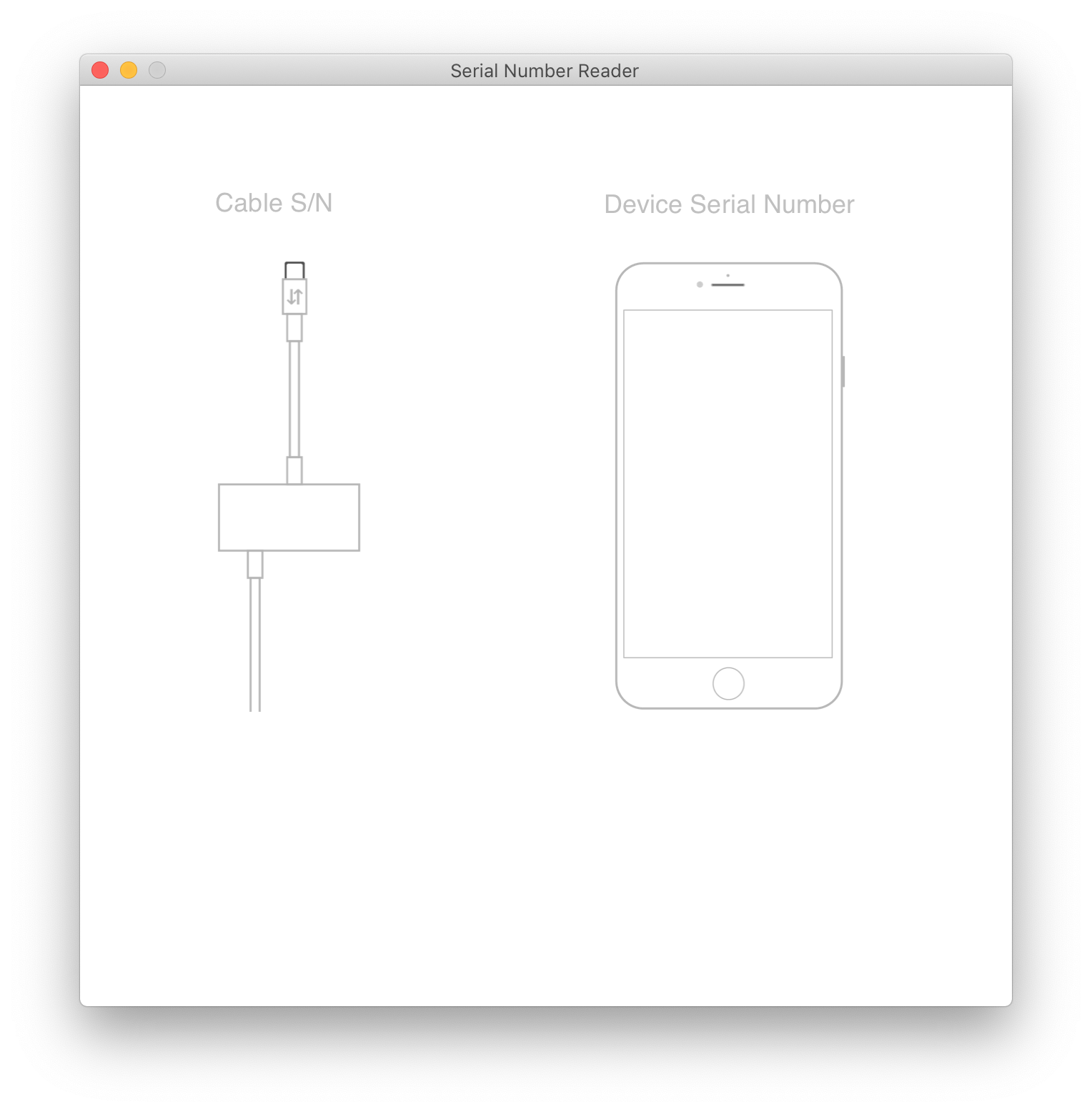
Another feature of Tristar that I would like to talk about is ESN. This is a small blob that Tristar stores in its EEPROM (on CBTL1610A2 and later). It can be obtained over IDBUS using the Serial Number Reader cable (or Kanzi, they are basically the same except for different USB-PIDs and slightly different enclosures)
Simply put, by sending this blob to ttrs.apple.com , you can get the serial number of the device ... This mechanism is used by Apple Store / Apple Premium Reseller employees to retrieve SN from dead devices (if Tristar is still alive):
What happens on IDBUS when an ESN is received, @spbdimka documented :
Training
The procedure for "Firmware» ESN called on Tristar training (provisioning). It takes place with diagnostics on the device side, via EzLink on the receiving side in three steps.
You can check the status using diags:
tristar --prov_stat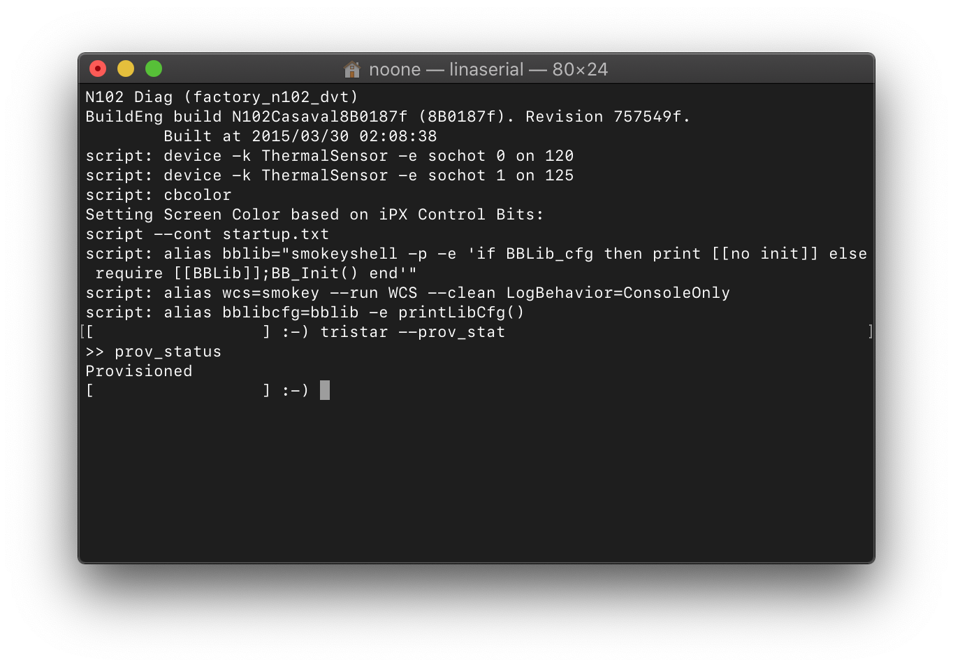
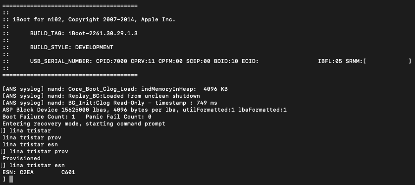
... and also get ESN:
tristar --esn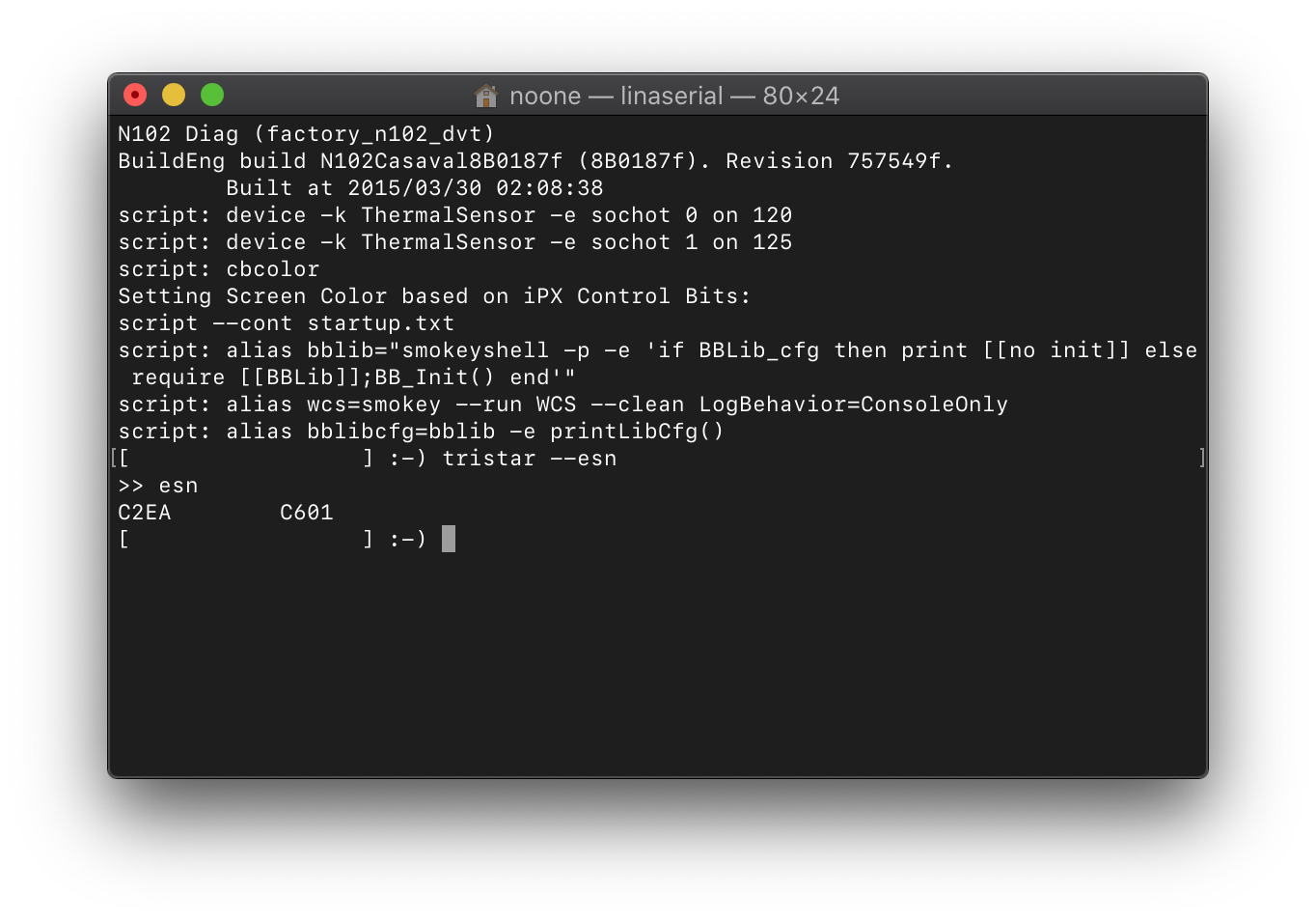
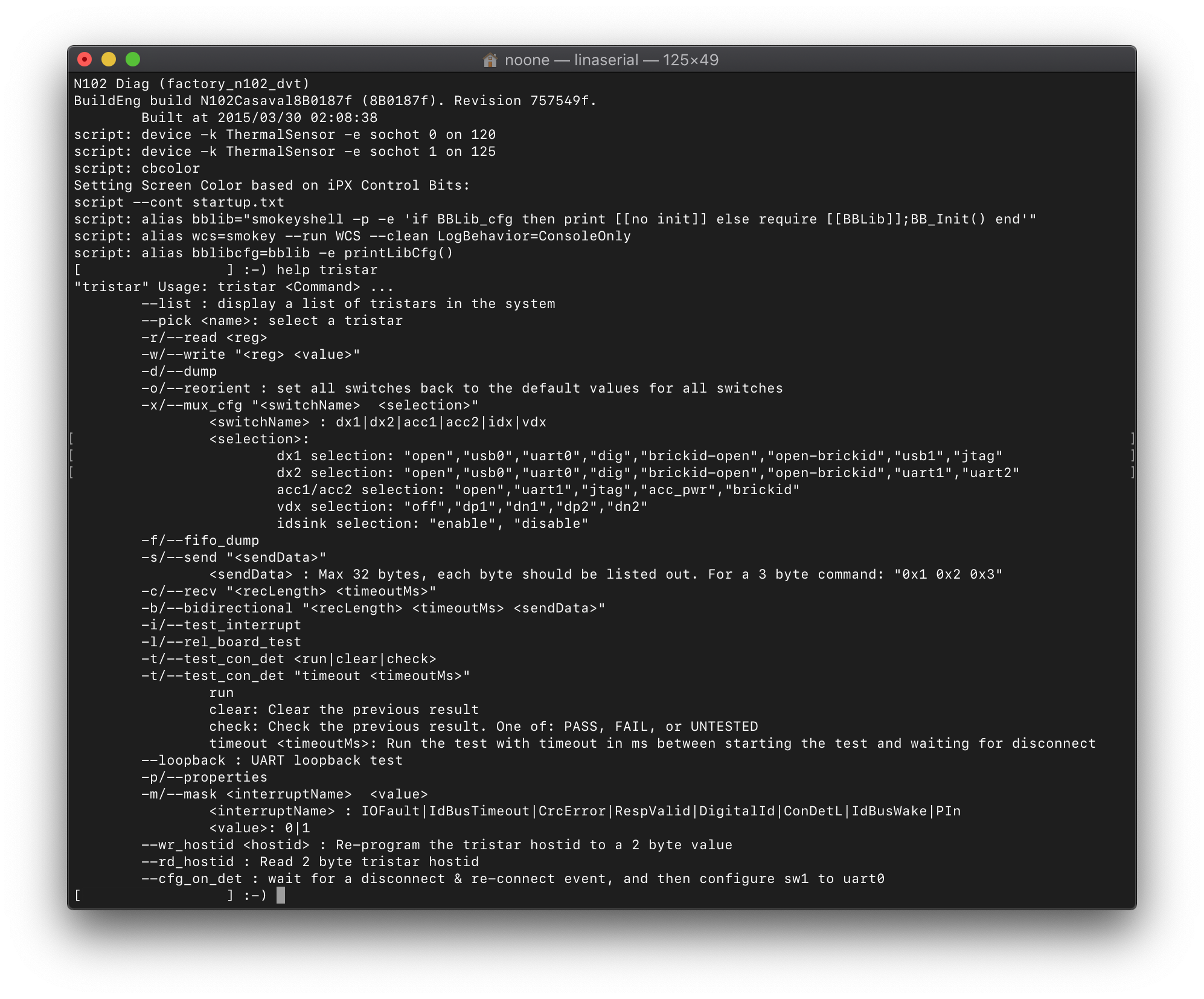
By the way, diags generally have a rich set of Tristar commands (available since iOS 7):
Tristar I2C
Tristar is available on the I2C bus (address 0x34 for writing, 0x35 for reading). This is how diag and kernel drivers interact with it. Not much is publicly known
about registries . A lot of information about the register map itself can be obtained from the leaked iBoot source code (only for THS7383 - seems to be backward compatible with CBTL1608 - and CBTL1610), but not much about what needs to be written there in order to achieve any interesting results. Another source of knowledge is the Tristar module from diags (easily retrieved through SWD while it is running). For example, I was able to reverse the provisioning and ESN read algorithms. Then I implemented this as an addition to my load for iBoot called Lina :
I also tried to change the ESN writing algorithm but failed - the mechanism is too complicated for me. However, code snippets from Lina are available here .
Electrical characteristics of the Tristar
The Tristar itself is powered by a 1.8V supply. The lines for IDBUS are 3.0V tolerant, according to my oscilloscope:
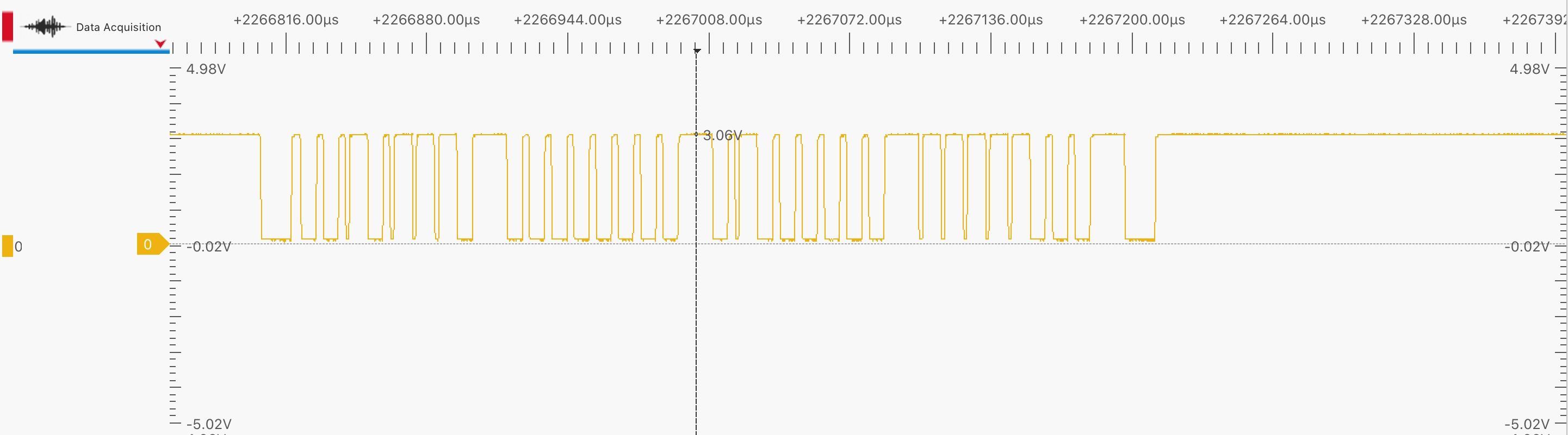
So without a level shifting circuit, it is better not to try to communicate with IDBUS using 5V tolerant devices like some Arduino models ...