What is I-IoT
After the introduction of the steam engine in 1760, steam was used to power everything from agriculture to textiles. This sparked the First Industrial Revolution and the era of mechanical manufacturing. At the end of the 19th century, electricity, new ways of organizing work and mass production came along, marking the beginning of the Second Industrial Revolution. In the second half of the 20th century, the development of semiconductors and the introduction of electronic controllers gave rise to the era of automation and the Third Industrial Revolution. At the 2011 Hanover Fair, Henning Kagermann, Wolf-Dieter Lucas and Wolfgang Walster coined the term Industry 4.0 for a project to renew the German production system using the latest digital technology.

Industry 4.0 is expected to be able to implement the following:
- Combine production with information and communication technologies
- Combine customer data with production data
- Make the most of machine-to-machine communication
- Manage production autonomously, flexibly and efficiently saving resources
The founder and president of the World Economic Forum, Klaus Schwab, believes that the independence of the fourth industrial revolution can be justified by three factors.
- The pace of development. Unlike previous ones, this industrial revolution is not progressing linearly, but rather exponentially. This is a product of the multifaceted, deeply interdependent world in which we live, as well as the fact that new technology itself synthesizes increasingly advanced and efficient technologies.
- . , , , . , «» «» , , «» .
- . , , .
By definition, IoT is the key to the further development of the industry, including technologies such as big data analytics, cloud technologies, robotics and, most importantly, the integration and convergence between IT and manufacturing.
The term I-IoT (Industrial internet of Things) refers to the industrial subset of IoT, which is the digital transformation of natural business. I-IoT makes business more flexible, more profitable, understandable and creates new digital value chains.
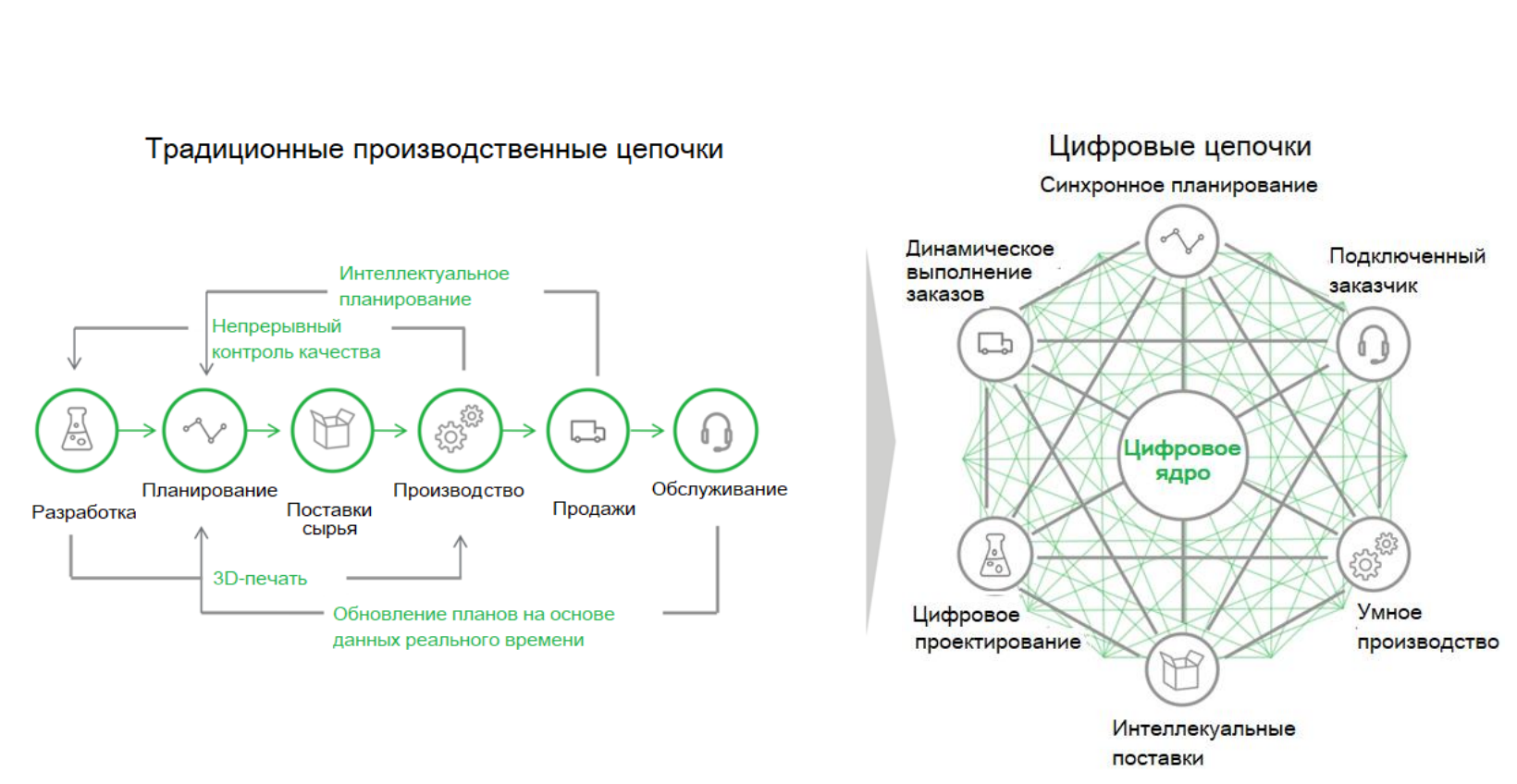
Traditional production chains are straightforward, sequential steps such as product development, sourcing and sourcing of raw materials, and product manufacturing and servicing. The essence of the new digital transformation is that a service ecosystem and new business models are being created around a certain digital core, giving new qualities to production. Such as cost reduction between different stages of production preparation, commissioning and operation. The links between different departments and stages are becoming faster, which makes it possible to work more efficiently and more competitively in the market.
The I-IoT is expected to create more business value and have such a profound impact on human society that it will usher in the Fourth Industrial Revolution.
According to Forbes:
- IoT 157 2016 457 2020 , 28,5%
- , , IoT 2020 , 40 .
IoT I-IoT –
- , . , , . , .
- , , ; .
- I-IoT , .
- — , , . I-IoT, , .
- .
- , . , , , .
- . I-IoT .
- , .
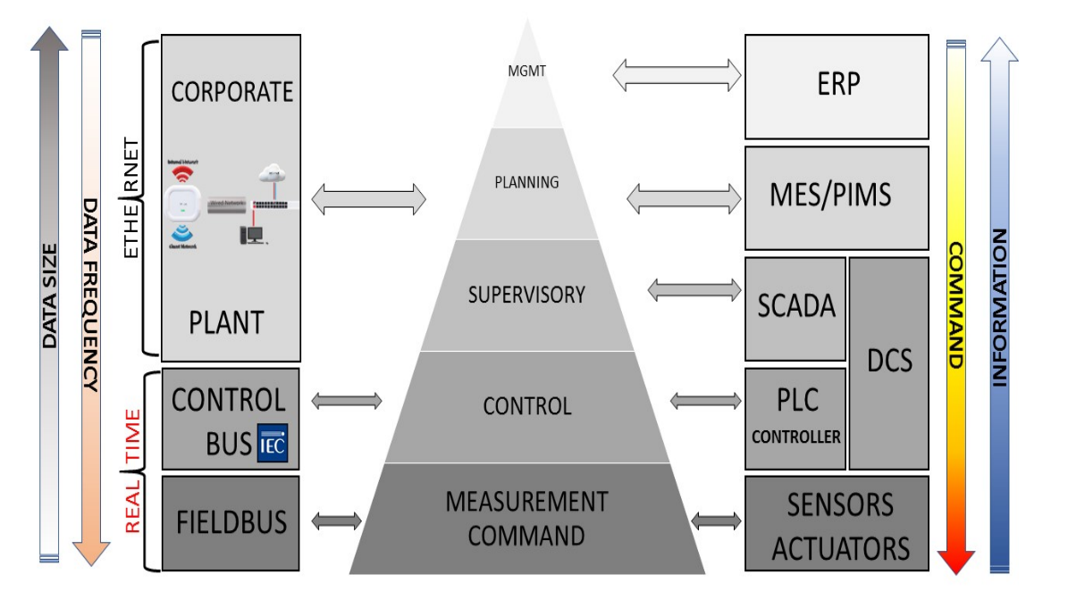
CIM (computer-integrated manufacturing) is a logic model for manufacturing systems developed in the 1990s to integrate manufacturing processes, automation systems, and information technology systems at the company or enterprise level. CIM should not be seen as a design method for creating automated factories, but rather as a reference model for the implementation of industrial automation based on the collection, coordination, sharing and transfer of data and information between different systems and subsystems through software applications and communication networks. The CIM is often depicted as a pyramid with six functional levels as shown in the following diagram
Level 1 - Sensors, Transducers and Actuator
An electronic sensor is a structurally complete measuring instrument capable of converting one or several physical quantities into an electrical signal for subsequent transformations, transmission, processing and display of measurement information. An actuator (actuator) is a device that converts a control command into a physical effect on the process. In fact, its function complements that of the sensor. The actuator accepts a control signal as an input to the control system and transmits energy as an output to the mechanism.
Level 2 - RTUs, microcontrollers, CNC, PLC and DCS
- (Remote terminal unit RTU) — , . , , . , .
- (Embedded controller), , , . .
- (CNC) – , . . , - .
- PLC — , . PLC , , , . , , , . 10 100 .
- DCS are commonly used in continuous processes such as refineries, power plants, or chemical plants. They combine both the control function implemented in the PLC and the supervisory control system (SCADA) function. While PLC and SCADA are two separate systems, each with their own address spaces, in DCS these systems use the same variables and data structures.
Level 3 - SCADA, Historian
The SCADA system is a software package for collecting, processing, displaying and archiving information about a monitoring or control object in real time. A data collection system (Historian) collects real-time information about the operating status of equipment. The SCADA system implements the following main functions:
- PLC, , RTU , CIM.
- , .
- , , .
- - (HMI).
- HMI PLC.
4 -MES
MES is a software system located between ERP and SCADA or PLC, designed to efficiently manage a company's production process. The main function of MES is to synchronize the management of the business and the manufacturing system by combining planning and control levels to optimize processes and resources.
The main features of the MES system are:
- Order management and production planning
- Management of incoming raw materials and semi-finished products
- Asset management and monitoring
- Production tracking
- Maintenance management
- Quality checking
Level 5 - ERP
ERP includes software packages that an organization uses to manage the day-to-day activities of their business, such as accounting, purchasing, project management, and manufacturing. ERP integrates and defines a set of business processes that govern the exchange of information and data between the systems involved. ERP collects and transmits transaction data from different departments of the organization, thus ensuring data integrity by acting as a single source.
Production networks
An integrated production system requires different types of communication networks, each dedicated to a specific task
- Level 1: fieldbus
- Level 2: network of controllers
- Level 3, 4, 5: corporate network
Field networks have been introduced to interface controllers, sensors and actuators, reducing the need for complex wiring. In the fieldbus, sensors and actuators are equipped with a minimum set of processing to ensure the transfer of information in a deterministic manner.
The controller network must provide communication between the PLC nodes. Data transmission must occur at specific intervals. Control networks and fieldbuses are also often referred to as real-time networks due to the timing of the transmission of data and information.
A corporate network is a network located between management systems and planning and management systems. This layer of the network should guarantee the processing of complex information, but in shorter periods of time. Therefore, there is no need for a tight time frame for this network layer.
OPC server
No other industrial communications standard has received such widespread acceptance among many industries and equipment manufacturers as OPC. It is used to integrate a wide variety of industrial and business systems. SCADA, security systems (SIS), programmable logic controllers (PLC), and distributed control systems (DCS) use OPC to communicate with each other, as well as with Historian databases, MES and ERP systems. The reason for the success of OPC is very simple - it is the only truly universal interface that can be used to communicate with a variety of industrial devices and applications, regardless of the manufacturer, software or protocols used in the control system. After the emergence of the OPC standard, almost all SCADA were redesigned as OPC clients,and each hardware manufacturer began to supply its controllers, I / O modules, smart sensors and actuators with a standard OPC server.
OPC classic (Data access DA)
In 1995, various companies decided to create a working group to define the interoperability standard. These companies were: Fisher Rosemount, Intellution, Intuitive Technology, Opto22, Rockwell, Siemens AG.
Microsoft members were also invited to provide the necessary support. The task of the working group was to define the standard of access to information in the Windows environment based on modern technologies of that time. The developed technology was named Object Linking and Embedding (OLE) for Process Control (OPC). In August 1996, the first version of the OPC was defined.
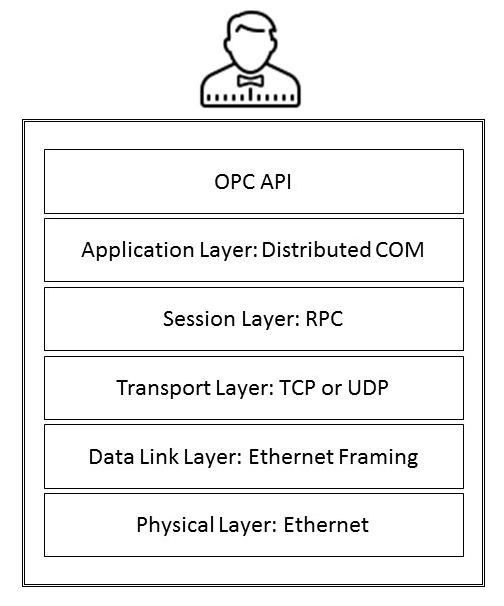
The following diagram shows the different layers of OPC Classic with the main communication protocols - COM, DCOM and Remote Procedure Call (RPC)
COM is a software architecture developed by Microsoft for building component applications. At the time, this allowed programmers to encapsulate reusable pieces of code in such a way that other applications could use them without worrying about the details of their implementation. COM objects can be replaced with newer versions without having to rewrite the applications that use them. DCOM are networked versions of COM. DCOM tries to hide from software developers the differences between COM objects running on one computer and COM objects running remotely on another computer. For this, all parameters must be passed by value. This means that when calling a function provided by a COM object, the caller must pass the associated parameters by value. On the other hand,The COM object will respond to the caller by passing the results by value as well. The process of converting parameters into data transmitted over the network is called marshalling. After marshaling is complete, the data stream is serialized, transmitted, and restored to its original data order at the other end of the connection.
DCOM uses the RPC mechanism to transparently transfer and receive information between COM components on the same network. The RPC mechanism was developed by Microsoft to allow system developers to request execution of remote programs without having to develop special procedures for the server. The client program sends a message to the server with the proper arguments, and the server returns a message containing the results from the executed program.
OPC Classic contains a number of limitations:
- available only on operating systems of the Microsoft Windows family;
- connection with DCOM technology, the source code of which is closed.
- configuration problems related to DCOM;
- inaccurate DCOM communications interruption messages;
- the inability of DCOM to exchange data over the Internet;
- inability of DCOM to ensure information security.
OPC Classic data acquisition model
The objectives of the OPC Classic standard are as follows:
- Structure data on the server side to make it easier to collect data on the client side.
- Define communication services and standard communication mechanisms
In essence, the OPC Classic standard works as follows.
The server manages all available data.
The server sends requests for data from devices on demand and updates the internal cache regularly. The server initializes and manages the cache for each group of variables requested by the OPC client. The scan rate on the OPC client side cannot be less than the scan rate of the OPC server to collect data from devices and update its internal cache. We recommend that you configure the OPC client to read from the cache and update it at twice the rate that the OPC server scans for devices. Each piece of data exchanged has its own meaning, indicated by its time stamp and quality. Data exchange includes reading, writing, and automatic updating when values change. Reading or polling is performed by the OPC client, which regularly sends requests for group data.The recording phase can be synchronous or asynchronous. Automatic updates uses the request rate provided by the OPC client. The OPC server checks for each update to see if the absolute value of the cached value minus the current value is greater than the client-specified dead zone multiplied by the range configured for that variable. It can be written like this:
if (abs(last_cached_value – current_value) > (PERCENT_DEAD_BAND/100) * range) {
//cache is updated, and the client is notified through a callback mechanism
}
Information from the OPC server is organized into groups of related items for efficiency. There are two different types of groups:
- Public groups: available to any client
- Local groups: only available to the client who created them
OPC UA
The OPC Foundation's first response to the growing limitations of COM and DCOM adoption was the development of OPC XML-DA. It retained the characteristics of OPC, but adopted a communications infrastructure that is not associated with either the manufacturer or a specific software platform. The conversion of OPC-DA specifications to web services-based versions has proven insufficient to meet the needs of enterprises that increasingly interact and integrate with the corporate and external world.
For information on the OPC UA architecture, see opcfoundation.org/developer-tools/specifications-unified-architecture .
Therefore, the OPC UA protocol was developed to replace all existing COM-based versions and overcome security and performance concerns. The standard addresses the need for platform-independent interfaces and allows the creation of extensible data models to describe complex systems without loss of functionality. OPC UA is based on the service-oriented approach defined by the IEC 62451 standard. It has the following objectives:
- Using OPC Components on Non-Windows Platforms
- Allows you to integrate its main components into small devices
- Implements standard communication across firewall based systems
From a technical point of view, OPC UA works as follows:
- API isolates client and server code from the OPC UA stack
- UA stack converts API calls to messages
- UA stack receives messages by sending them to client or server via API

OPC UA information model
Basic principles of information modeling in OPC UA:
- Using object-oriented methods including inheritance hierarchy.
- The same mechanism is used for accessing types and instances.
- Information is made available through the use of fully connected nodes in the network.
- Data type hierarchies and links between nodes are extensible.
- There are no restrictions on how to model information.
- Information Modeling is always hosted on the server side.
The set of objects and related information that the OPC UA server makes available to clients is the address space. You can think of the address space as an implementation of the OPC UA information model.
An OPC UA address space is a collection of nodes that are linked by links. Each node has properties called attributes. A certain set of attributes must exist on all nodes. The relationship between nodes, attributes and links is shown in the following diagram
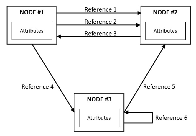
Nodes can belong to different classes of nodes, depending on their specific purpose. Some nodes can represent instances, others can represent types, and so on. OPC UA has eight standard node classes: variable, object, method, view, data type, variable type, object type, and reference type. In OPC UA, the most important node classes are object, variable, and method.
OPC UA sessions
OPC UA provides a client-server communication model that includes state information. This state information is session related. A session is defined as a logical connection between a client and a server. Each session is independent of the underlying communication protocol; any problem at the protocol level does not automatically end the session. The session ends after an explicit request from the client or due to client inactivity. Idle intervals are set during session creation.
OPC UA security model
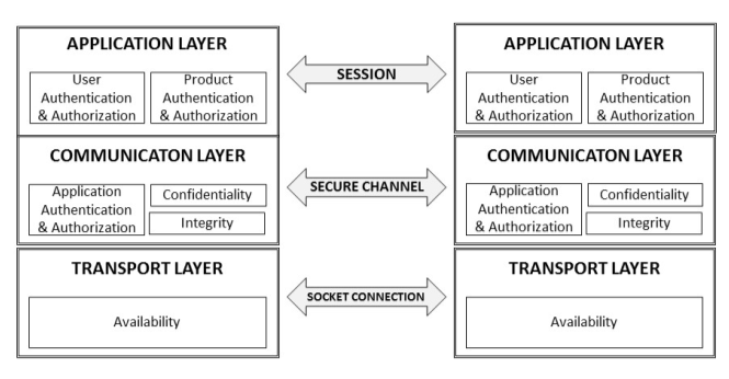
The OPC UA security model is implemented by defining the secure channel on which the session is based. The secure channel exchanges data as follows:
- Ensures data integrity using digital signatures.
- Provides privacy through encryption.
- Authenticates and authorizes applications using X.509 certificates.
The figure shows the following layers: application layer, session layer, and transport layer.
The application layer is used to transfer information between clients and servers that have established an OPC UA session. The OPC UA session is established on a secure channel. The transport layer is the layer responsible for sending and receiving data over a socket connection, to which error handling mechanisms are applied to ensure that the system is protected from attacks such as denial-of-service (DoS).
OPC UA data exchange
The easiest way to exchange data between an OPC UA client and a server is to use read and write services. Read and write services are optimized for transferring a group of data, rather than a single piece of data or multiple values. They allow you to read and write either the values or the attributes of the nodes. The read service has the following parameters:
maxAge: This is the maximum time it takes to get the values. This is indicated by the client. It forces the server to contact a device (such as a sensor) if the copy in its cache is older than the maxAge parameter configured by the client. If maxAge is set to zero, the server should provide the current value, always reading it directly from the device.
Time stamp type: OPC UA defines two time stamps: the source time stamp and the server time stamp. The original timestamp is the timestamp that comes from the device, and the server timestamp is the timestamp that comes from the operating system that the OPC UA server is running on.
The list of nodes and attributes looks like this:
- NodeId
- AttributeId for instance value
- DataEncoding: this allows the client to choose an appropriate data encoding, and the defaults are XML, UA binary
Features of the OPC protocol
The OPC protocol cannot be fully called free. To develop software using the OPC SDK, you must be a member of the OPC Foundation. However, now there are free implementations of the client and server library, for example freeopcua.github.io , but they do not yet have a pub / sub implementation.
Compared to other protocols like MQTT, OPC is not lightweight.
PLC programmable logic controller
The term PLC (Programmable Logic Controller, PLC) was subsequently defined in the EN 61131 (IEC 61131) standards. PLC is a unified digital electronic control system specially designed for use in industrial environments. The PLC constantly monitors the state of the input devices and makes decisions based on the user program to control the state of the output devices.
Requirements for PLC:
- It must be able to function in harsh industrial conditions, such as temperature extremes, dirt, poor-quality power supply network.
- It should operate with industry-specific 24VDC or 240VAC discrete input and output signals, as well as analog signals (± 10V, 4-20mA, etc.)
- The programming language must be understood by automation engineers
- The PLC must continuously monitor the operation of the industrial facility
- The operating system must be fast enough to perform a scan cycle (20 - 100ms)
The following figure shows the structure of the basic operating mode of the PLC (using the example of CPU Simatic).

OPC UA with SIMATIC S7-1500
Prerequisites - Simatic TIA Portal V13 - 16 must be installed
To simulate a controller with an OPC server, you must install and configure SIMATIC S7-PLCSIM Advanced version 2 or 3.
support.industry.siemens.com/cs/document/109772889/trial -download% 3A-simatic-s7-plcsim-advanced-v3-0? dti = 0 & lc = en-WWI have installed simulator version 3 on a system with an existing Simatic TIA Portal V14 SP1 package. Before installation, the installer notified that PLCSIM V14 is not compatible with SIMATIC S7-PLCSIM V3 and must be removed. I followed these steps, after which the installation was suspended. A test project has been created in the TIA Portal with the CPU 1512C-1 PN. A special feature was that it became impossible to perform simulation using the "Start simulation" button, but the "Dowload to device" button works when PLCSIM Advanced is running.
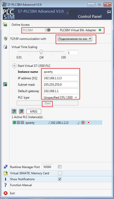
To access the simulator over the network, you must enable PLCSIM Virtual Eth. Adapter, for which you must first install the WinPcap software. Next are the standard Ethernet settings.
After pressing the "Start" button, the simulator becomes active and visible on the network
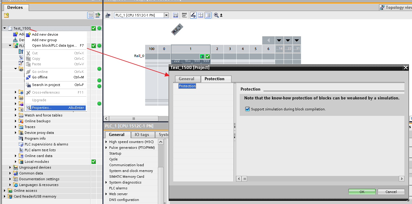
Next, you need to set the "Support simulation during block compilation" checkbox on the "Protection" tab in the dialog box for calling the "Properties" shortcut menu in the project root
The next step is to activate the OPC server in the project and select the type of license (you can overlook it, after which the project will not be compiled)

Further, the process of uploading software to PLCSIM Advanced is similar to uploading to a standard simulator, with the exception of the one described earlier.
In the TIA Portal test project, DB1 was created with one tag “pressure” and the digital output “Q0.1 Tag_2” was assigned.
To connect to the OPC server and monitor the network, nodes and tags, you can use the UaExpert OPC client, which can be downloaded from www.unified-automation.com/products/development-tools/uaexpert.html .
To connect to the OPC server, you need to add a new connection and register the Endpoint Url, previously set in the OPC server project settings in the TIA Portale, in my case it is opc.tcp: //192.168.1.113: 4840

When you connect the OPC client to the simulator server, you can observe the nodes and tags created.

To programmatically implement the interaction of the OPC client and server, you can use the opensource implementation of the library in Python github.com/FreeOpcUa/python-opcua , there are also examples with code. Before using, you need to install the necessary dependencies:
pip install freeopcua
pip install cryptography
The simplest example of creating an OPC server with three tags
from opcua import Server
from random import randint
import datetime
import time

class Opc:
    def __init__(self):
        self.server = Server()
        self.url = "opc.tcp://127.0.0.1:4848"
        self.server.set_endpoint(self.url)
        self.namespace_uri = "OPCUA_SIMULATION_SERVER"
        self.namespace = self.server.register_namespace(self.namespace_uri)
        self.root_node = self.server.get_objects_node()
        self.parameters = self.root_node.add_object(self.namespace, "Parameters")

    def create_variable(self, name, initial=0):
        variable = self.parameters.add_variable(self.namespace, name, initial)
        variable.set_writable()
        return variable

def main():

    opc = Opc()
    tag_1 = opc.create_variable("Temperature", 25)
    tag_2 = opc.create_variable("Pressure")
    tag_3 = opc.create_variable("Time")

    opc.server.start()
    print("Server started at {}".format(opc.url))

    while True:
        #tag_1.set_value(randint(10, 50))
        tag_2.set_value(randint(200, 999))
        tag_3.set_value(datetime.datetime.now())

        time.sleep(2)

if __name__ == '__main__':
   main()
The same simplest example of the client part
from opcua import Client
import time

url = "opc.tcp://127.0.0.1:4848"

client = Client(url)

client.connect()
print("Client connected")

Temp = client.get_node("ns=2;i=2")
Temp.set_value(25)

if __name__ == '__main__':
    while True:
        temperature = Temp.get_value()
        print(temperature)
        time.sleep(1)
It is also possible to observe the connection using the UaExpert client

I-IoT Edge concept
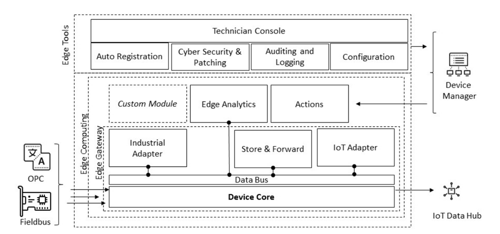
Edge is the hub between the production environment and the IoT world in the cloud. Edge can be decomposed into three macro components: Edge Gateway, Edge tools, Edge Computing
In 2017, Gartner announced the following: "The Edge will eat the cloud." While this statement may sound a bit controversial, it highlights the role Edge has played over the years. Industrial companies, after a phase of transition to the cloud, realized that it is not always possible to do everything in a remote location. The reasons for this are as follows:
- . . , , . .
- : . , , , , 1 50 .
- Network latency: Advanced process controls or analytics associated with data changes to profile equipment behavior in a small time window suffer from high and variable network latency. Optimization of equipment is necessary for the fastest execution within a certain time interval.
- Data connection. To optimize the workflow or service the equipment, it is required to replace components without access to the Internet connection.
Edge Gateway
The edge gateway is the core of the edge device. The main duty of the edge gateway is to connect to an industrial source to collect and send data to the I-IoT hub using a transmission protocol such as MQTT, CoAP, HTTPS or AMQP.
The most important components of an edge gateway are the industrial adapter and the IoT adapter. An industrial adapter usually subscribes to data from the Field area and publishes it on the data bus. Typically, it implements the connector for the selected device, acting as a source in the I-IoT data stream and making it available on the Edge data bus. An IoT adapter, on the other hand, receives values from the data bus and transmits them to the IoT Data Hub. An important part of the Gateway Edge is the Store-and-Forward component. It is a general mechanism for storing data in temporary local storage. It provides robustness of data transmission against network instability. In the global network, the instability and latency of the communication channel are very high. The storage and forwarding mechanism can be as follows:
- Limited memory buffer that covers a short period of inactivity
- A dedicated storage area on disk that can accommodate long periods of inactivity or huge data traffic.
The range of the time window during which the data transfer must be ensured depends on the specific scenarios and the physical resources of the edge memory and storage.
Configuration utilities (Edge tools)
Edge tools should have the following features:
- The ability to easily manage and configure data collection both remotely and locally
- Possibility to register for fixes and updates
- Possibility of logging actions
- Ability to view and modify data using the user interface
- Self-configuration and self-registration in the cloud at startup
- Ability to receive and execute commands from the cloud
Edge Computing
Edge computing has the following features:
- Ability to perform actions using I-IoT (middleware) software, both offline and online.
- Possibility to host custom applications
- The ability to run analytics offline, in conjunction with I-IoT middleware or remotely.
- Ability to perform actions or load analytics from I-IoT middleware
- Ability to send unstructured and specific data to I-IoT middleware on demand or on conditional startup
Edge implementations
Cloud vendors and original equipment manufacturers (OEMs) develop various solutions based on their own operating system or offer cloud-independent software development kits (SDKs).
Azure IoT Edge
Azure IoT Edge is Microsoft's Edge solution for Azure IoT. The platform supports storage and forwarding, Edge Analytics, and multiple adapters for converting native or standard protocols to Internet protocols. Azure IoT Edge also supports OPC Server in its OPC Classic and OPC-UA implementations. Product overview:
- Works with Linux or Windows devices that support container subsystems.
- Free, open source, MIT-licensed runtime
- Docker-compatible containers from Azure services or from Microsoft partners Cloud frontend. Allows you to remotely administer and deploy workloads from the cloud using IoT Hub
Greengrass
Greengrass is the next generation of IoT Edge from AWS. AWS provides the SDK for building AWS Edge and extends cloud capabilities to edge devices with Greengrass. This allows devices to take action locally while still using the cloud for management, analytics and persistent storage. Greengrass supports OPC UA, and does not support OPC Classic. Benefits:
- Near real-time event response
- Work offline
- AWS IoT Greengrass authenticates and encrypts device data, both over the LAN and with the cloud
- Simplified device programming with container support
Android Things
Google provides an SDK for Edge development. It sponsors Android as the next generation of Edge devices. Platform features:
- Development with Android SDK and Android Studio
- Access to hardware such as display and camera through the Android platform
- Connecting the app to Google services
- Integration of additional peripherals via peripheral I / O API (GPIO, I2C, SPI, UART, PWM)
- Using Android Things Console to Send Updates Over the Air and Security Updates
Node-RED
It is a visual programming tool for the Internet of Things that allows devices, APIs, and online services to connect to one another. The Node-RED runtime is built on top of Node.js and therefore makes the most of its event-driven, non-blocking model. Node-RED is a streaming programming tool originally developed by the IBM Emerging Technology Services team and currently part of the JS Foundation.
Features:
- Create program logic directly in the browser
- The Node-RED runtime is built on top of Node.js
- Streams (logical units) created in Node-RED are saved to JSON files that can be easily exported and imported
- Running is possible on any device that supports node.js
- A huge number of extensions
Intel IoT Gateway
Features:
- Cloud and enterprise connectivity.
- Connectable to sensors and existing controllers.
- Pre-filtering the selected data for delivery.
- Local decision making to ensure easy connectivity to legacy systems.
- Hardware data encryption and software locking.
- Local computing and analytics on the device.
Flogo iot
Project Flogo is a lightweight, open source Go-based ecosystem for building event-driven applications. Triggers and actions are used to process inbound events. The interaction interface provides key capabilities such as application integration, stream processing, etc.
- Integration Flows Application engine with conditional branching and visual development environment
- Streaming is a simple pipeline-based stream processing action with the ability to aggregate events across multiple triggers and aggregate across time windows.
- Declarative rules for real-time contextual decisions
- Microgateway pattern for content-based conditional routing, JWT validation, rate limiting, circuit breaking, and more
Eclipse kura
Eclipse Kura is an open source, extensible IoT Edge Framework based on Java / OSGi. Kura offers API access to the hardware interfaces of the IoT gateways (serial ports, GPS, watchdog, GPIO, I2C, etc.). It includes ready-to-use field protocols (including Modbus, OPC-UA, S7), an application container, and web-based visual programming for data acquisition, processing and publishing to cloud platforms.
EdgeX Foundry
EdgeX FoundryTM is a vendor-neutral open source project supported by the Linux Foundation that creates a common open environment for IoT edge computing. At the heart of the project is an interoperability infrastructure hosted on a complete OS-independent reference software platform to create a plug-and-play ecosystem that unifies the market and accelerates the deployment of IoT solutions.
Edge connectivity options for industrial data sources
- Edge on fieldbus
- Edge on OPC DCOM
- Edge on OPC Proxy
- Edge on OPC UA
- OPC UA on the controller
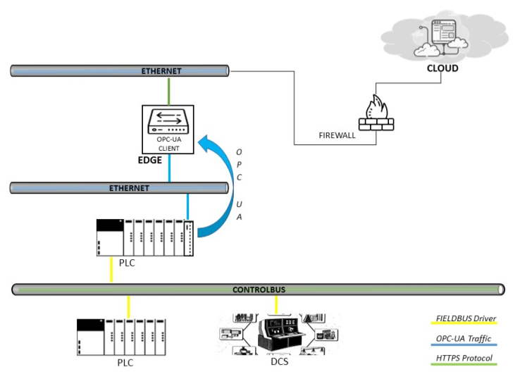
Edge on OPC UA and on the controller
Connecting to an OPC UA server is the preferred scenario as it maximizes the capabilities of OPC UA. The connection to the OPC server can be deployed in two different ways. In the first case, Edge connects to the OPC UA server through its OPC UA client interface. The data source can be one of: PLC, DCS, SCADA, or Historian.

In the second case, the Edge connects to the OPC server installed directly on the PLC, as previously discussed with the Simatic CPU 1500.
MQTT protocol
Pub / sub is a way to separate a client sending a message from another client receiving a message. Unlike the client / server model, clients are not aware of any physical identifier such as an IP address or port. MQTT is a pub / sub architecture, not a message queue. Message queues, by their very nature, store messages, while MQTT does not. In MQTT, if no one subscribes to (or listens to) a topic, it is simply ignored and lost.

The client sending the message is called the publisher; the client receiving the message is called the subscriber. At the center is the MQTT broker, which is responsible for connecting clients and filtering data. Such filters provide:
- filtering by topics - by design, customers subscribe to topics and certain topic branches and do not receive more data than they want. Every posted message must contain a subject and the broker is responsible for retransmitting this message to subscribers or ignoring it;
- content filtering - brokers have the ability to check and filter published data. Thus, any data that is not encrypted can be managed by the broker before being stored or transferred to other clients;
- filtering by type - a client listening on a stream of data to which it is subscribed can also apply its own filters. Incoming data can be analyzed, and depending on this, the data stream is processed further or ignored.
There are three levels of quality of service in MQTT:
- QoS-0 ( ) – QoS. « », . ;
- QoS-1 ( ) – . , PUBACK;
- QoS-2 ( ) – QoS, , . - . QoS-2, PUBREC. , PUBREL. PUBREL . PUBREL PUBCOMP. PUBCOMP , .
At the moment, there are two versions of the MQTT protocol specification: 3.1.1 and 5.0 . A more detailed description of the protocol can be found here or a recording of my presentation github.com/vladipirogov/Message-Queue-Telemetry-Transport , www.youtube.com/watch?v=fYoGubQFz5c&t=5s and www.youtube.com/watch?v=8mupuCjedlc .
In the next article I will try to show an example of the implementation of a custom Edge I-IoT platform using Node-red as an Edge Gateway, Apache Kafka as a data manager and temporary storage, Kafka Streams as a Rule Engine, Mosquitto (another implementation is possible) as an MQTT connector ... InfluxData technologies will be used to store time series data.
Link to the video of the meetup.
Sources of information
- Digital transformation platform
- OPC Unified Architecture Specification
- Encyclopedia of ACS TP
- FreeOpcUa is a project to implement an open-source (LGPL) OPC-UA stack and associated tools.
- GR Kanagachidambaresan Internet of Things for Industry 4.0
- Max Hoffmann Smart Agents for the Industry 4.0
- Wolfgang Mahnke OPC Unified Architecture
- Klaus Schwab Fourth Industrial Revolution
- Perry Lee Internet of Things Architecture
- Ismail Butun Industrial IoT
- MQTT specifications