no, the story begins in 2015, when I got acquainted with FPGAs. In my first simple works, I formed the clock I needed from the counter and fed all the logic from it (naturally, provided that I needed the clock slower than it was fed to the FPGA, for example UART and SPI). Naturally, they chased me for this, but I had a simple excuse “but it works!”, And everything really worked. Since then, the thought has crept into my head: "Where can I get the timing signal from?"
There are not many options for sources to take a shred. Either take from a certain ClockWizard based on PLL or MMCM, or form it from a counter, or immediately from the leg, so to speak, single ended. What if we take the clock signal generated by the FPGA primitive?
As part of this article, I decided to consider three options: a multiplexer (MUXF7), a truth table (LUT1) and short-circuit the FPGA legs to themselves.
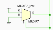
In the case of a multiplexer, the output is fed to the control signal, and the input signals are pulled to 0 and 1.
In the case of LUT, we short-circuit the output to the input and set the inverting truth table. When supplying "1", output zero, and when supplying "0", output one.

In the case of GPIO, everything is simple there, the output signal is assigned the inverse of the input signal:
| assign s2 = ~ s1; |
The purpose of the experiment: to generate a frequency in three ways and measure it.
We will measure the frequency at the expense of counters. There will be 4 counters: three for each option and one basic counter, relative to which everything will be counted. And we will watch these counters through ChipScope.
And here is the entire module code:
module gen_clk(
    input clk_base,
    input s1, //gpio
    output s2 //gpio
    );

//  -
assign s2 = ~s1;
wire clk_gpio = s1;
reg [31:0] cnt_gpio = 0;
 (* MARK_DEBUG="true" *) reg [31:0] cnt_gpio_buf = 0;
always@(posedge clk_gpio)
begin
    if(cnt_gpio[2:0]==3'd0) cnt_gpio_buf<=cnt_gpio;
    cnt_gpio <= cnt_gpio + 1'b1;
end

//
wire clk_mux;
MUXF7 MUXF7_inst
(
    .O(clk_mux),
    .I0(1'b1),
    .I1(1'b0),
    .S(clk_mux)
);
reg [31:0] cnt_mux = 0;
 (* MARK_DEBUG="true" *) reg [31:0] cnt_mux_buf = 0;
always@(posedge clk_mux)
begin
    if(cnt_mux[2:0]==3'd0) cnt_mux_buf<=cnt_mux;
    cnt_mux <= cnt_mux + 1'b1;
end
//
wire clk_lut;
LUT1#(
    .INIT(2'b01)
)
LUT1_inst(
    .O(clk_lut),
    .I0(clk_lut)
);
reg [31:0] cnt_lut = 0;
 (* MARK_DEBUG="true" *) reg [31:0] cnt_lut_buf = 0;
always@(posedge clk_lut)
begin
    if(cnt_lut[2:0]==3'd0) cnt_lut_buf<=cnt_lut;
    cnt_lut <= cnt_lut + 1'b1;
end
//
 (* MARK_DEBUG="true" *) reg [31:0] cnt_base = 'd0;
always@(posedge clk_base)
begin
    cnt_base <= cnt_base + 1'b1;
end

endmodule
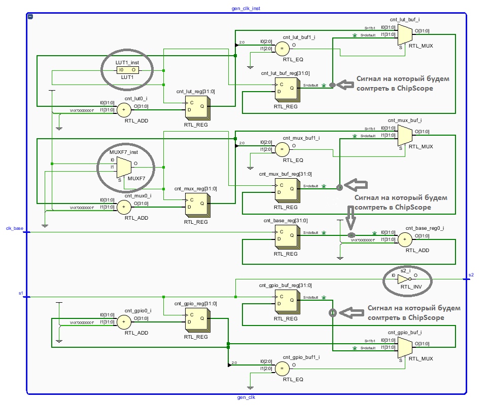
Here is a schematic of the project. The primitives are circled, and the arrows indicate the signal that will be entered into the ChipScope for frequency analysis:
Practical part I
have three boards at my disposal:
- KC705 Evaluation Kit

- ML507 Evaluation Kit

- Chinese Spartan-6 XC6SLX16 board

Looking ahead, , .
And so now the actual results
Kintex-7:
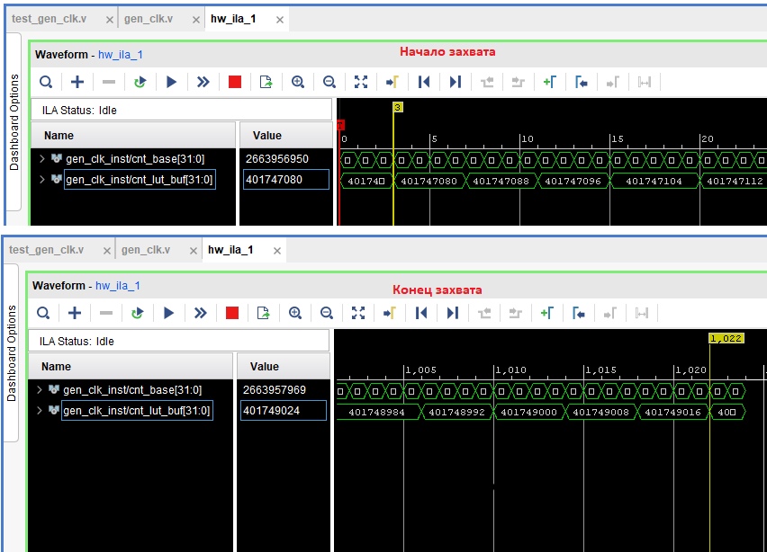
Since the project began to be made for it, the project was not written entirely at once, but in stages. First, I connected one LUT, added signals to debugging and began to watch.
The base counter is clocked at 200 MHz, so it is not difficult to calculate the frequency of the clocks generated on the loot, how many times the delta counter of the loot counter is the delta of the basic counter at the same time, so many times its frequency. In this case: the frequency generated by the loot is 381.55 MHz.
Now we will add a multiplexer to the project, and by analogy with one loot, we will calculate the frequency for it, and for the loot (after all, something must change).
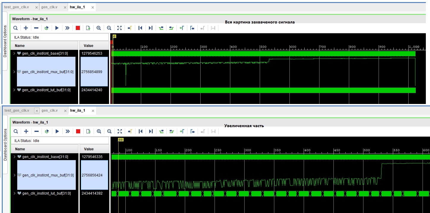
The first thing that catches a glance is how much the counter rattles. This affects the huge frequency of the multiplexer, but in general it is clear that the counter is increasing, which means that it can also be taken and counted. Eventually:
- Multiplexer frequency: 5953.89 MHz
- Loot frequency (changed): 379.98 MHz
Well, at the end, let's add a closed loop from a GPIO pair to the project. The KC705 board has SMA connectors J13 and J14. Here I closed them with a conductor about 10 cm long.As a result:
- GPIO frequency: 90.59 MHz
- Multiplexer frequency: 12994.13 MHz
- Loot frequency: 380.18 MHz
Let's replace, for the sake of experiment, the conductor with a longer one, I have a wire twice as long. As a result, the frequency dropped to 85.29 MHz.
At this stage of the experiment, it can be noted that the frequency of operation of primitives in FPGAs is not the same. In the case when there was only one loot, then the synthesizer chose the fastest loot and built a circuit around it, then when the multiplexer was added, the synthesizer tried to find that super position where both the loot and the multiplexer work as quickly as possible, and these are other elements and frequencies that are already slower. When external pins were added, the entire project on a crystal was basically relocated to these legs and the project began to be synthesized on nearby elements, for some reason, in that place, the frequencies of the loot and multiplexer increased noticeably, but do not forget that against the background of all this, to the project a ChipScope with a depth of 1024 and a data bus from 64 to 128 is connected (it changes from project to project). Now let's move on to the next board.
Virtex-5:
I did not go all the way that I went with the previous board, I immediately added all 3 options for generating a cloak and looked in ChipScope what happened.
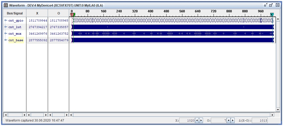
The figure shows two labels X and O. As well as their values in the columns, the format of numbers is unsigned decimal. It is worth noting that the base counter now counts at 100 MHz. And so the result:
- GPIO frequency: 96.34 MHz
- Multiplexer frequency: 614.41 MHz
- Loot frequency: 5761.1 MHz
It can be seen that on this board the loot turned out to be faster than the multiplexer, and the frequency of the pins turned out to be higher than on the first board, perhaps this is because I connected the two pins not with a 10 cm conductor, but with a jumper, as a result, the communication line became shorter, and the frequency was higher.
And now the last option with a Chinese board.
Spartan-6:
There are two basic counters in ChipScope, in fact it's the same counter just didn't want to reconfigure ChipScope. In this project, the basic counter is clocked at 50 MHz.
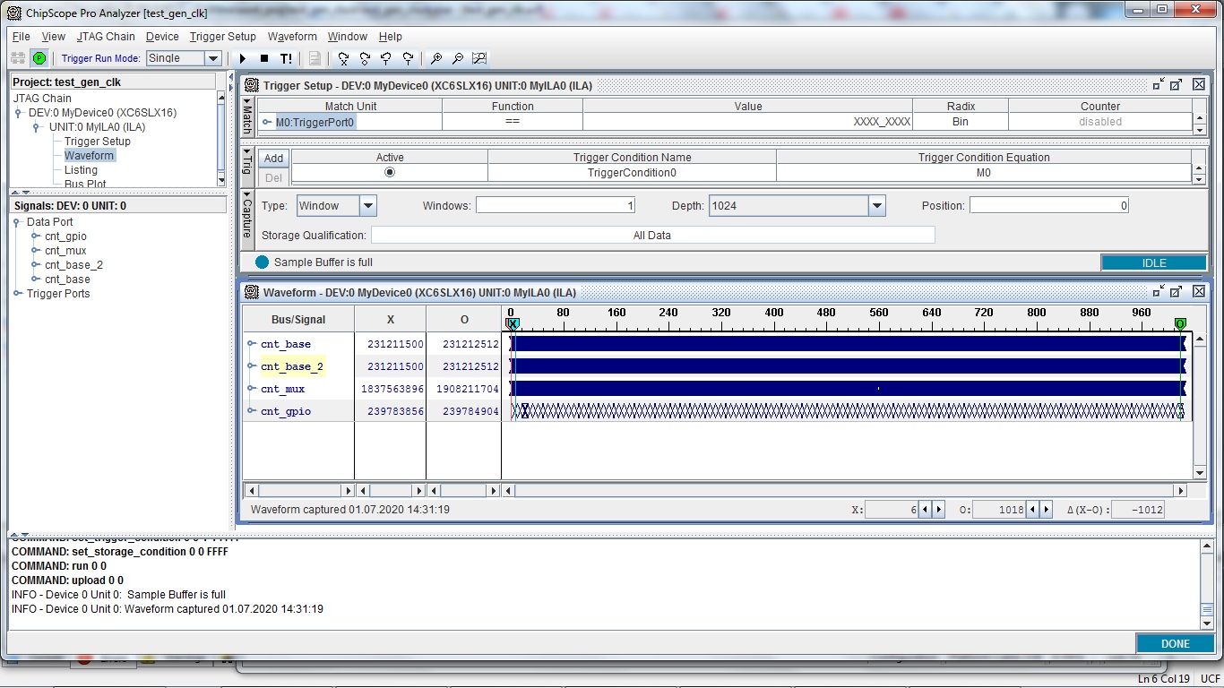
In the case of this board, everything turned out to be much more complicated. Firstly, the project did not want to be synthesized in any way in the form that was synthesized in the previous versions. Secondly, in the end I had to throw out the LUT, I tried to replace it with a five-way one, but it didn't work either. In general, here are the results:
- GPIO frequency: 51.77 MHz
- Multiplexer frequency: 3 490 504 MHz
- Loot frequency: failed to collect
The results in the performance of this board turned out to be not at all happy, and not only because the loot could not be used as a chunk, but also because of the incredibly huge frequency of the multiplexer. As for the shred generated on the legs, a conductor of about 25-30 cm was used, at the end closed with a wire, parasitic capacitances and inductances were probably formed there, which had their effect on the generation of the shred.
Conclusion
In general, we managed to generate clock signals on various primitives, and we also managed to see (using the Kintex-7 as an example) that primitives have different latency depending on their location. On my own behalf, I want to add that I do not consider the experiment carried out to be completely correct, for example, the bit width of the counters was not calculated, the signal transfer from different clocking domains was not taken into account (although I made the signal in the buffer stay for several clocks), the ChipScope itself should ideally be removed and another way should be found analyze the generated frequency.
Problems encountered:
Vivado ISE , . :
- set_property ALLOW_COMBINATORIAL_LOOPS TRUE [get_nets -of_objects [get_cells gen_clk_inst/LUT1_inst]]
- NET «s1» CLOCK_DEDICATED_ROUTE = FALSE;