Continuation of the series of articles about Model-Based Design. In previous episodes:
- Model-Based Design - How Not to Repeat Chernobyl
- Model-Based Design. Brushless DC Motor
- Model-oriented design. Creation of a reliable model, using the example of an aircraft heat exchanger
- The Glitz and Poverty of Model-Based Design for Aeronautical DO-331 Standards
In this series, authors Yu. N. Kalachev and A.G. Aleksandrov, present a mathematical model of an active rectifier in a structural modeling environment.
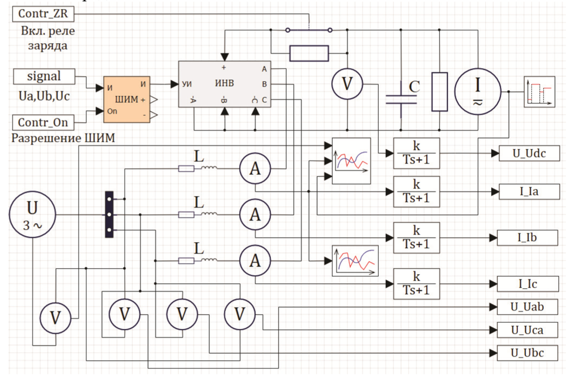
Active rectifiers are widely used in converter technology to ensure an active nature of the exchange of energy with the grid. They are a bi - directional AC-DC converter with unity power factor and low non-harmonic distortion. The basis of the device is a three-phase bridge inverter connected to the network through a three-phase inductor (see Fig. 1).
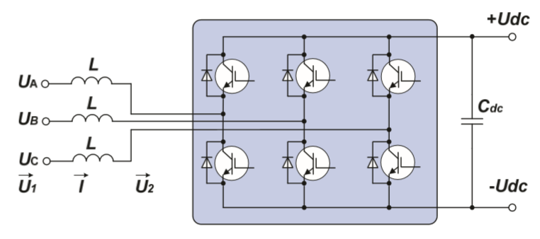
Fig. 1 - Schematic diagram of an active rectifier
1. How does it work?
, (Udc) .
Cdc</sub> , (, ). , .
( ) , . , , .
, π/2. , π/2, . , , .
( ) , π/2, . .
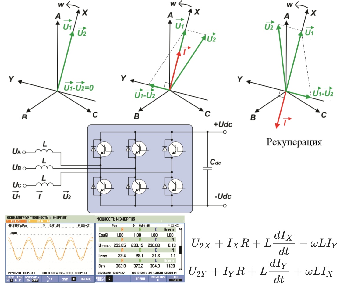
.2 , .
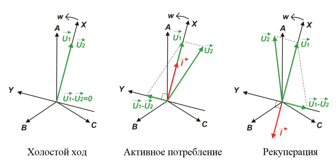
. 2 –
:
vecU1 —
vecU2 — ,
vecU1- vecU2 —
vecI —
ABC – ,
XY – , X .
.2 : ±90º, , .
, , , (Udc). . - IGBT- .
2. Mathematical description of the active rectifier operation
For the circuit in Fig. 1, you can write the following expression:
vecU1= vecU2+ vecI cdotR+L cdot fracd vecIdt
where:R is the active resistance of the inductor;
L is the inductance of the choke.
For a rotating coordinate system XY associated with the voltage vector of the input network, we can write:
Where:
for 50 Hz
- active component of the input current (coincides with the phase of the network);
- reactive component of the input current (lags behind or outstrips the network phase by 90º).
In order for the corrector's consumption pattern to be active, ...
In addition, the corrector must provide the functions of a rectifier, that is, maintain a given value , regardless of the load current.
3. The structure of the control system of the active rectifier
Consider the structure of the system based on its model in SimInTech (Fig. 3).
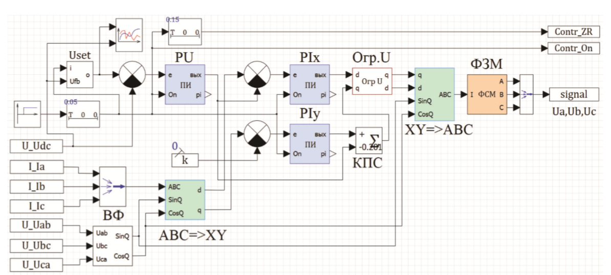
Fig. 3 - block diagram of the model
XY . (), .
() ().
:
Uset – Udc,.
– , .
ABC=>XY – , Y, .
XY=>ABC – Y .
PU – (), .
Ix – , .
Iy – , Y .
.U – Y — .
— (. 1.1). X, Y.
– — .
:
- – . , , . , , . =>XY , , XY => , . , , .
- , , SimInTech ( , help ).
4.
.4.
. 4 –
:
L = 0.0015
= 10 000
– 8.33
5.
, . – 160 — 1 () .
(.5, 6 7).
1 – , .
2 – (700).
3 – (50) .
4 – (-50) .
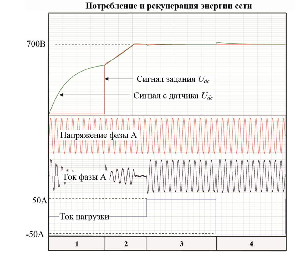
. 5
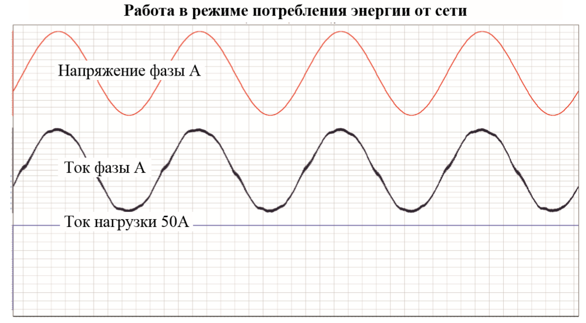
. 6
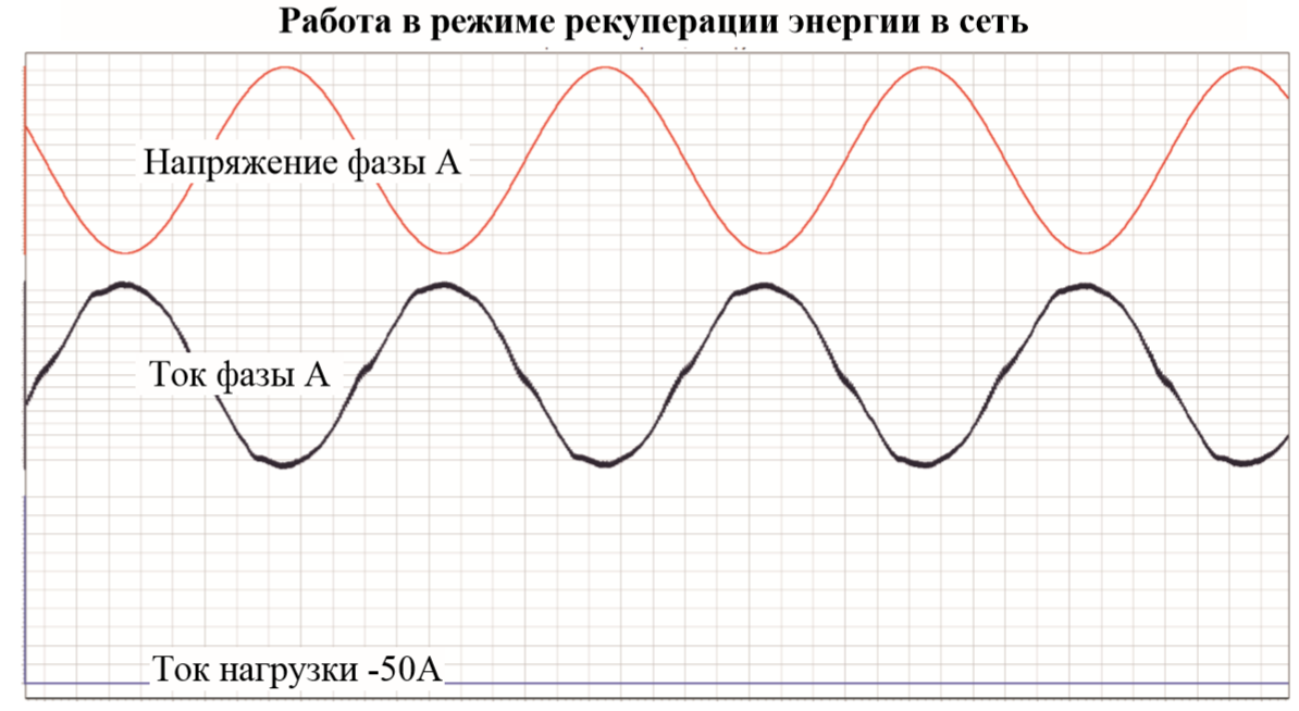
. 7
. SimInTech 4.4% .
.8 .
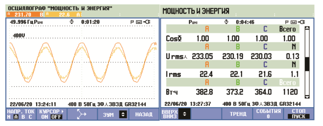
Fig. 8
It can be stated that the current and voltage are in phase and Cosφ = 1
For communication with the author Yuri Nikolaevich Kalachev (Kalachev_i@mail.ru)
For more information on the Electric Drive toolbox, follow the link:
http://3v-services.com/books/978-5-97060-766-4/?yclid=3971894245794548684