
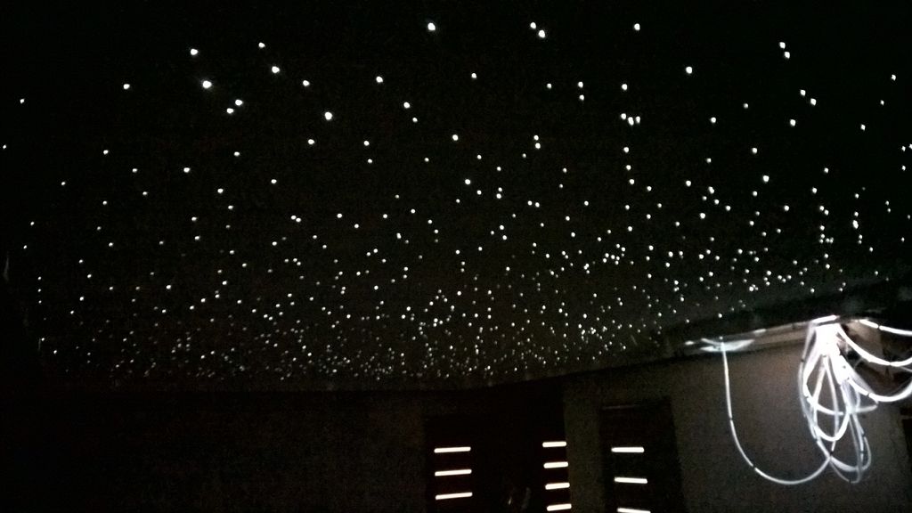
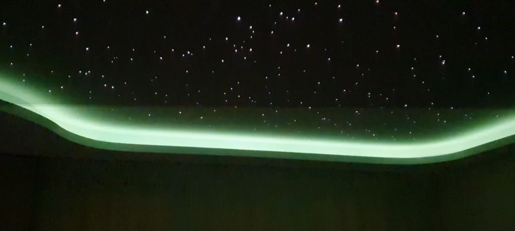
Want to see a piece of the galaxy on your ceiling? How to do this is described below.
For several years I have dreamed of completing this project, and now it is finally ready. It took a long time to implement it, but the final result was so great that it was worth it.
A bit about the project itself. I tried to do everything with my own hands to the maximum, which gave me complete creative freedom. As a result, I have the constellations of the northern hemisphere, control over star clusters using the remote control (brightness and color), reaction to music, control of the backlight, and, most importantly, the ability to change anything.
I chose Arduino as the platform for all this because I am familiar with its programming. The MSGEQ7 chip was responsible for responding to music - the Internet is full of its descriptions. For communication, I used the NRF24L01 that was lying around with me. To control a large number of LEDs, the PCA9685 servo controller was a good fit. If you want to do something simpler and cheaper, you can search Amazon for ready-made sets, but if you are interested in doing everything yourself, like me, then you will need the following skills:
- Familiarity with Arduino programming.
- Experience in the development of electrical circuits and soldering.
- Working with alternating current.
Many people ask me the cost of the entire project. It's quite difficult to give a specific figure, since I spent a lot of materials, and it all depends on which part you decide to do on your own, on the size of the project, etc., however, I think that it can fit into the fork from several hundred to a thousand dollars. I worked on it on weekends, and it took me about a year to complete everything.
Step 1: planning
First you need to decide whether to buy an electronic part or do it yourself. Making circuits requires an understanding of Arduino and electronics fundamentals, and besides, there is a chance to mess up somewhere. You can find many kits on Amazon and other stores under the phrase "Fiber Optic Star Ceiling Kit", so there are tons of options. But if you need complete creative freedom and control, then it's better to do everything yourself.
Having decided on the electronics, it is worth thinking about the structure of the ceiling, the size of the star map, and the number of stars. I chose the option with a conventional plasterboard ceiling. I have a low ceiling, and it was quite difficult to install optical fiber, so I settled on a relatively small number of stars, 1200 pieces, but the result was still amazing.
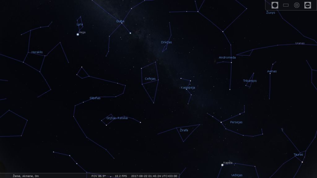
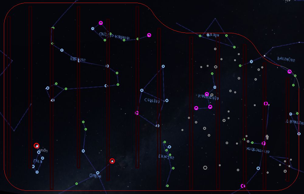
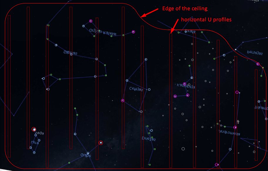
Now for the choice of the star pattern. I live in the northern hemisphere, so I chose the part of the sky that is visible here. A lot of applications show pictures of constellations - I used Celestia (as in this tutorial for making my own starry sky). Naturally, no one forces you to make a picture of the starry sky realistic and on the right scale - here you have complete creative freedom, and on the Internet you can find a bunch of ideas.
Step 2: materials
Now that everything is planned out, you can order materials.
I will not list materials for the ceiling itself, it all depends on the system used and other factors. I used a Knauf ceiling. The same applies to tools - most of them you need only to install the ceiling. To install the stars themselves and the electronics themselves, not so much is required - see the list. I bought a lot of things in local stores, and ordered the rest on AliExpress - it's cheaper, and the quality is usually acceptable.
For stars and electronics you will need:
- , . , . 12 , 30 , 350 15 . 14,4 /, .
- 3 . , 5 , 7 , 35 15 Arduino. RGB 5 , , .
- RGB 3 ( 5 , ). , , .
- 12 .
- . . , , . .
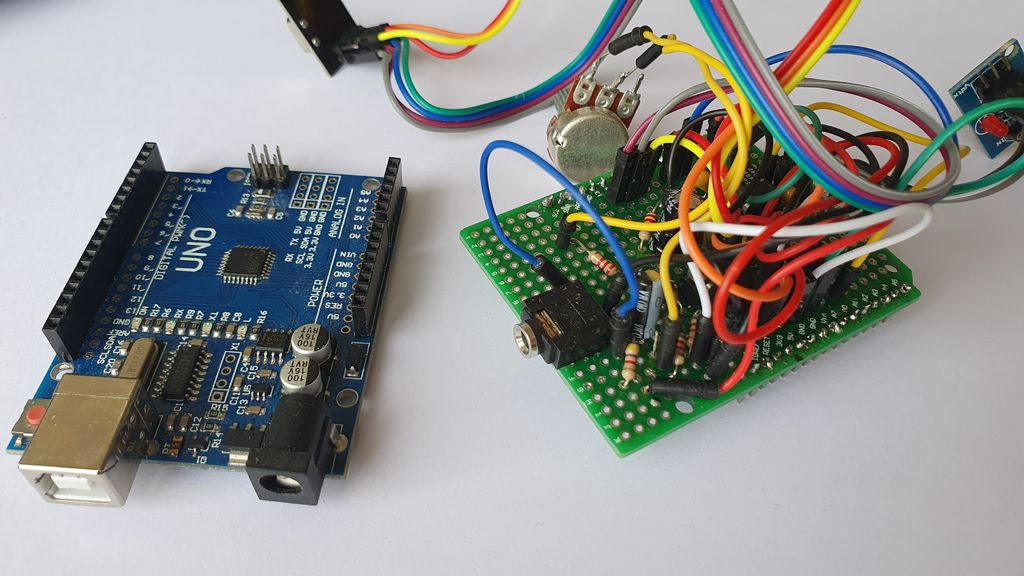
- PCA9685. 5- RGB .
- Arduino Uno/Mega × 2.
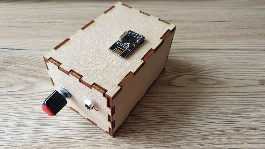
- NRF24L01 × 2.
- USB- Arduino.
- IRL540N. . 1 . – 5 . , . – .
- 2N2222 ( n-p-n). 3 . 15×3.
- Resistors 2W 10Ω / 2W 6.8Ω / 2W 6.8Ω for R, G and B per 3W LED respectively. 5 pull-up resistors, 10 kΩ, 0.25 W each.
- 10 uF capacitors for decoupling NRF24L01.
- Aluminum plate for fixing and cooling 3W LEDs.
- Boards for circuits.
- Development Boards for testing.
- Screws, plywood, duct tape and everything that is in any workshop.
- A bunch of wires of different thicknesses. For PWM signals, thin wires can be used for prototyping, but for LED strips and 3W LEDs, the thickness of the wires must be calculated depending on the distance from the circuit to the LEDs.
For remote control and spectrum analyzer:
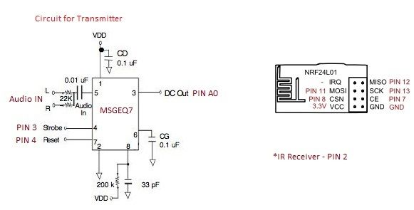
- MSGEQ7 × 1
- Resistors - 1 × 470 Ω / 1 × 180k Ω / 1 × 33k Ω.
- Capacitors: 1 × 33 pF / 1 × 0.01 μF / 1 × 0.1 μF.
- Thermal grease for processors.
- IR remote control and photodiode for the receiver
- A bunch of thin wires.
- Small breadboard. I used Proto Shield.
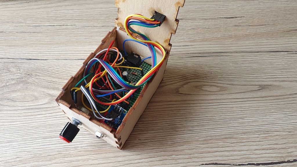
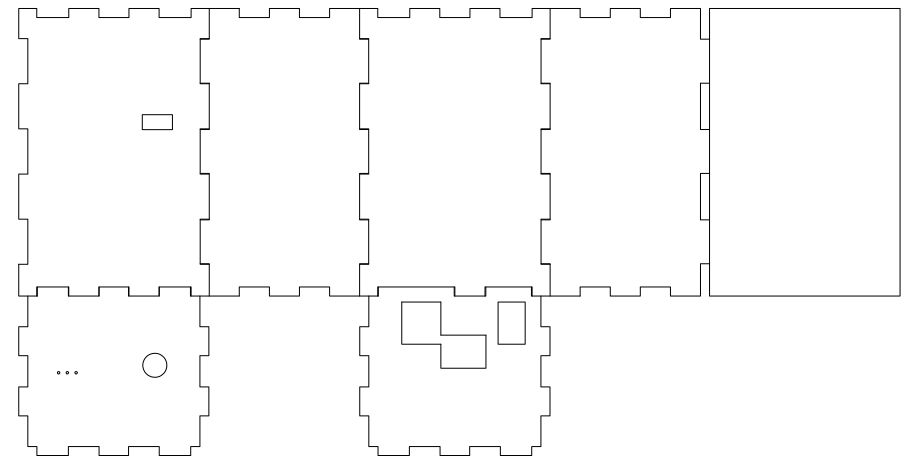
- Small case for Arduino. I made the body using laser cutting.
- Other components related to the main circuit. Their number is indicated in the list of components of the main circuit
Tools for installation and soldering:
- Transparent adhesive that does not dissolve fiber. I used a simple stationery.
- Soldering equipment.
- A multimeter will not be superfluous.
- Screwdriver.
- Pliers.
- An awl or something similar for making holes in the ceiling. The thickness is the same as the thickness of the optical fiber.
Step 3: installing the ceiling
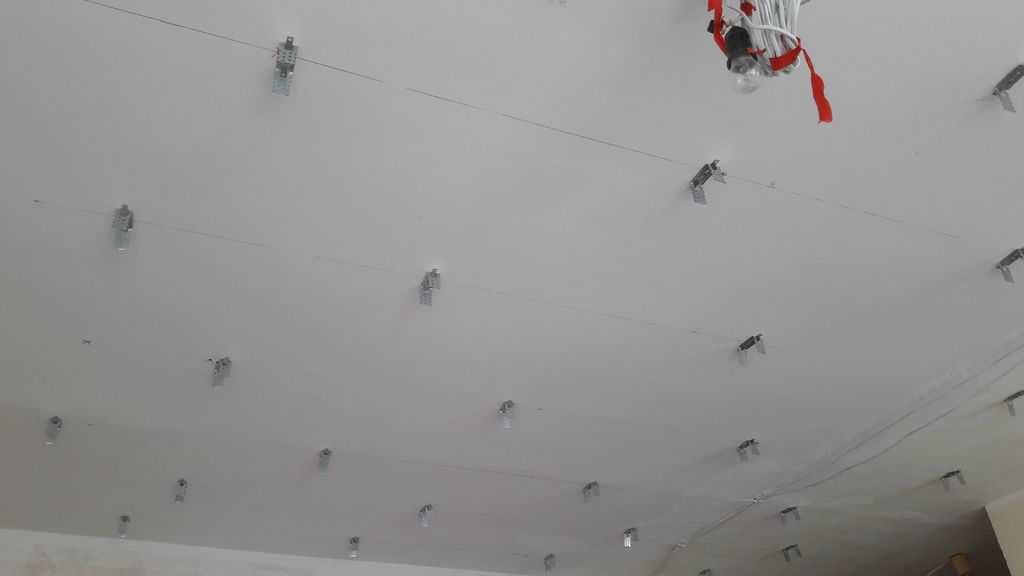
I will not paint the installation in detail - there is a bunch of materials on the network for installing a suspended ceiling, and I am not an expert in this matter. This approach is more complex than the usual star bar solution that most people choose. But on the other hand, I got a high-quality suspended ceiling, which looks absolutely normal during the day.
Especially for the maintenance of electronics, I made a hatch in the most inconspicuous part of the ceiling.
At this step, putty and primer are done, and painting is done after installing the fiber.
Step 4: Install Fiber Optic
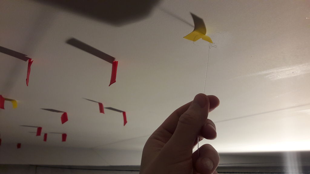
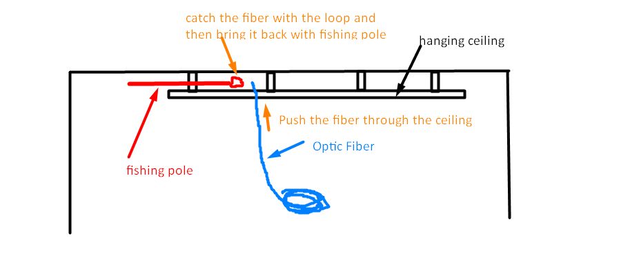
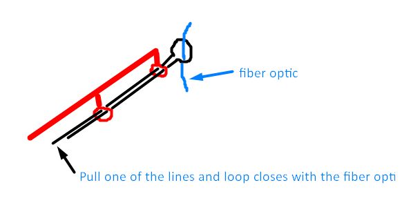
It took me longer than I expected ... After a lot of different improvisations, we agreed that in our case the best way to place the fiber is with a fishing rod and a loop of fishing line - see my skillfully executed scribbles with explanations. Now this idea seems laughable to me - but who doesn't like to mess around sometimes.
Considerations:
- I recommend sticking the fiber in the holes to prevent it from falling out. The adhesive should be transparent and not react with fiber. I used a simple stationery.
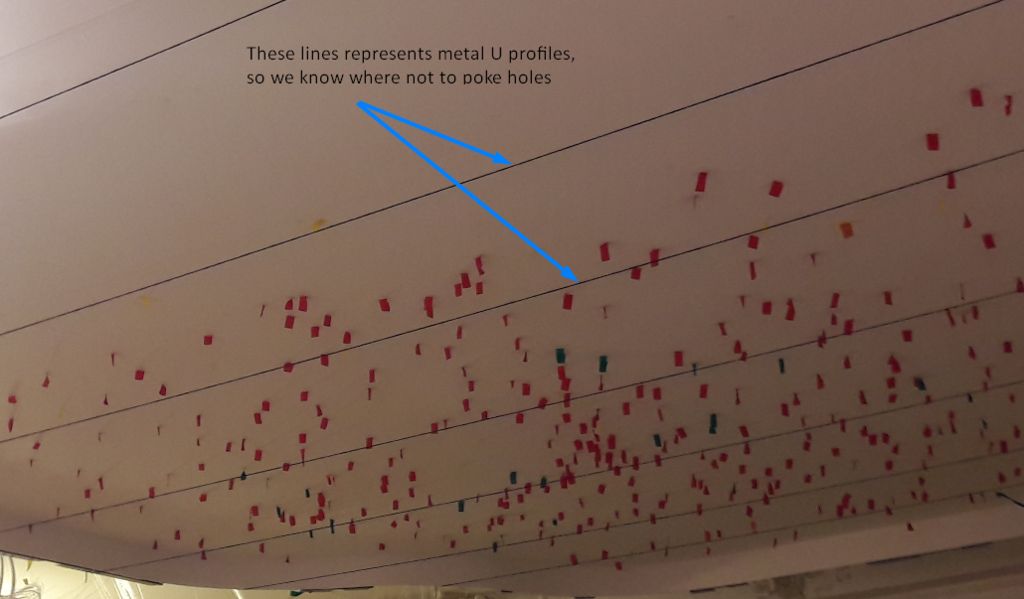
- You do not need to drill, the holes can be made with a simple awl, the same diameter as the fiber.
- I only used a tape measure to mark the exact locations of the stars. Not 100% accurate, but ok. To print a map of the sky, the ceiling was too big.
Step 5: finishing the ceiling finish - painting
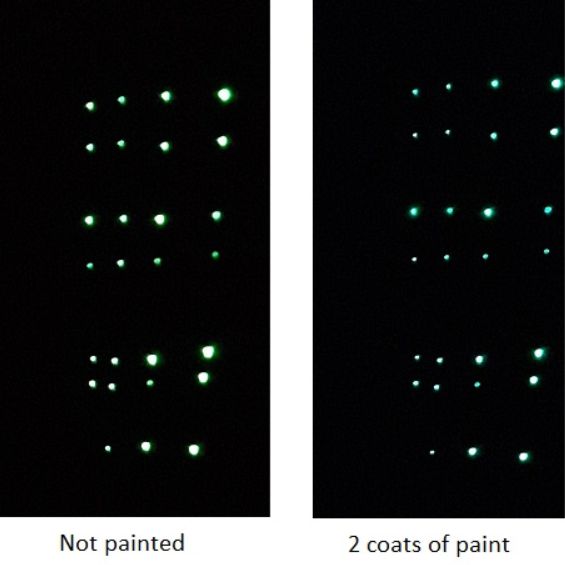
We painted directly over the fiber, so when it is off it is not visible. Everything looks like a regular ceiling. After two coats of paint, the brightness of the fiber remained almost the same.
Step 6: trial layout
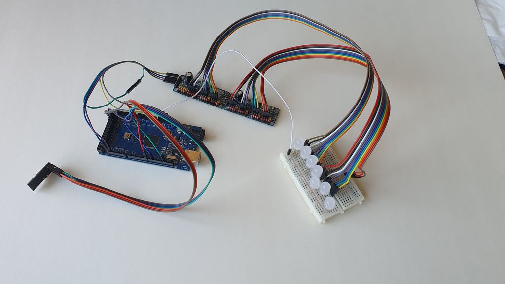


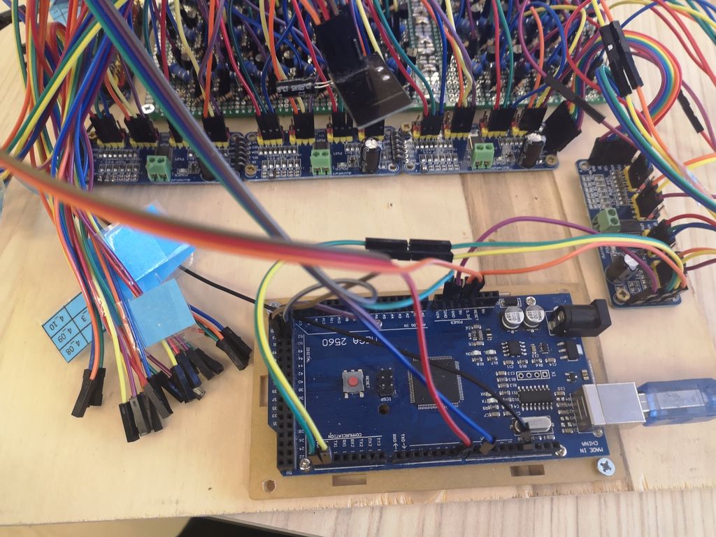
The scheme itself is not very complicated, and it worked for me right away. However, it is always better to check first, and then install - especially since in this case there is a lot of soldering. It is also convenient to have a test version for future updates - I think no one wants to short-circuit a project that took several days to install in the ceiling.
My test version is one or two PCA9685, NRF24L01 boards and power supplies connected to Arduino. Everything can be done on breadboards. The same applies to the remote control circuitry - they came across everything on the breadboard, and checked that everything works. I would also recommend soldering a few 3W LEDs for testing.
Step 7: code for Arduino
I have collected libraries and other useful links in the "useful information" section. For an explanation of how the code works, see the comments to it.
I wrote this code using various resources, some of which I have listed in the “Useful Information” section. However, since I finished the project over a year ago, by the time I decided to write this article, I could no longer find some of them, and some of the saved links were no longer working.
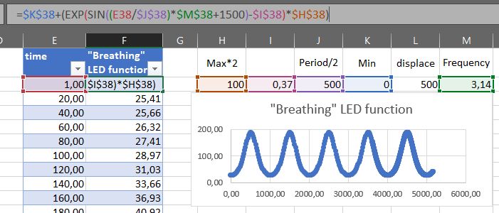
The code contains a rather complicated function for blinking LEDs. To improve the look, I used the tutorial on how to make breathing blinking: sean.voisen.org/blog/2011/10/breathing-led-with-arduino
The human eye does not perceive the brightness of light linearly, so a simple linear increase in brightness looks unnatural.
Receiver
code Transmitter code
Step 8: connect wires and LED strips
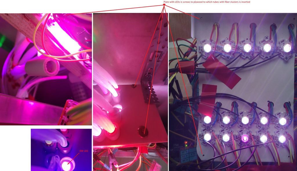
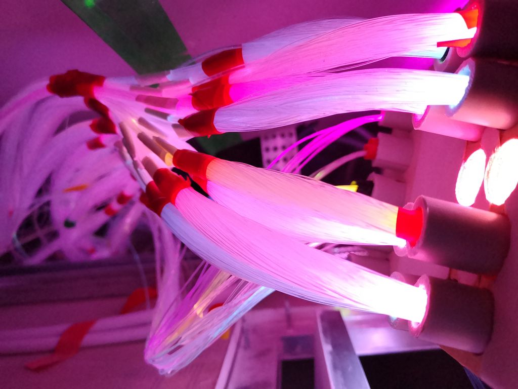

Final Connect Time! If everything is checked and everything works, the connection should go through without any problems - just soldering a bunch of identical components. For the convenience of servicing the entire circuit, I made a box of plywood in the size of a technical hatch - so if necessary, I can simply remove the entire circuit from the ceiling. I ran the fiber through plastic plumbing pipes, the size of which is roughly the same as 3W LEDs, and then I drilled holes of the same diameter in the plywood and inserted them there. Thus, I can easily disconnect the fiber from the LEDs as needed.
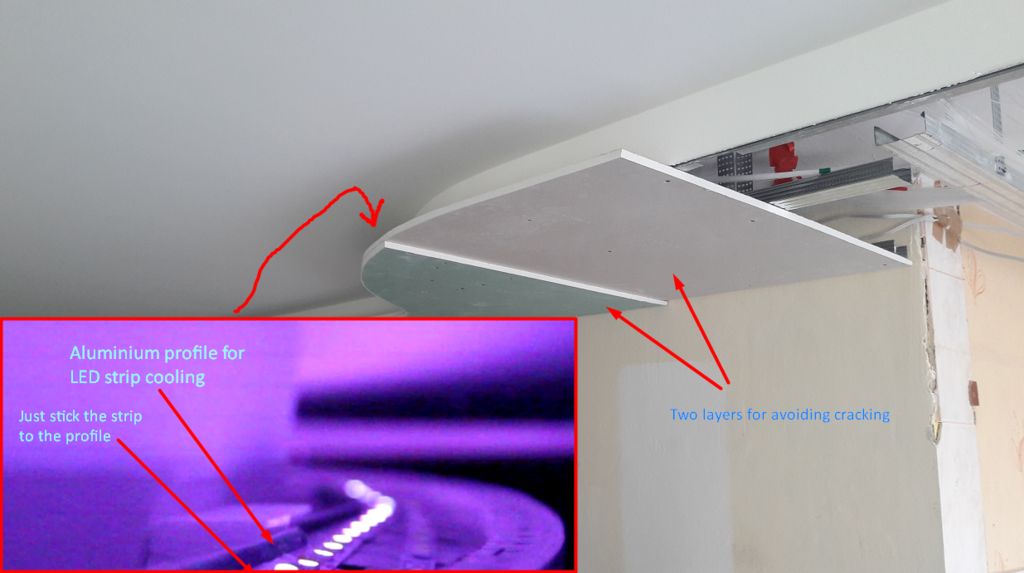
I suggest mounting LED strips on aluminum plates for cooling, since they are very hot.
Step 9: debug and tweak
Let's say you tested the circuit, but after you installed it, it doesn't work ... or something else doesn't work as expected. Then the problem is most likely in soldering - if everything worked in the test assembly, then it should in the final one too. I hope this is not your case, but as an example I will give one of the problems that I myself have encountered.
When I lowered the brightness of the LEDs to the minimum, the strips could stop working or start flashing. After spending a huge amount of time researching and debugging, I found that the problem was with the IRL540's slow switching, and the solution was simply lowering the PWM frequency to 50 Hz. The problem was almost resolved and the blinking remained only at the lowest values - however that doesn't matter since I don't use them. The problem came back when I decided to shoot a video about this ceiling, since such a small frequency is clearly visible on cameras - it's the same as shooting a TV. To solve this problem, I assembled a small circuit on a breadboard using 2N2222 transistors instead of IRL540, just for shooting video.
Now that everything is in place and working, you can do fine-tuning the brightness of the stars, reacting to music, fading modes and everything else.
Step 10: useful information and links
References
www.sparkfun.com/datasheets/Components/General/MSGEQ7.pdf
www.baldengineer.com/msgeq7-simple-spectrum-analyzer.html
rheingoldheavy.com/msgeq7-arduino-tutorial-01-getting-started
www.instructables.com/id/How-to-build-your-own-LED-Color-Organ-Arduino-MSGE
arduinoinfo.mywikis.net/wiki/Nrf24L01-2.4GHz-HowTo
learn.adafruit.com/16-channel-pwm-servo-driver/overview
github.com/adafruit/Adafruit-PWM-Servo-Driver-Library
github.com/z3t0/Arduino-IRremote
MSGEQ7
www.sparkfun.com/datasheets/Components/General/MSGEQ7.pdf
www.baldengineer.com/msgeq7-simple-spectrum-analyzer.html
rheingoldheavy.com/msgeq7-arduino-tutorial-01-getting-started
www.instructables.com/id/How-to-build-your-own-LED-Color-Organ-Arduino-MSGE
Nrf24L01
arduinoinfo.mywikis.net/wiki/Nrf24L01-2.4GHz-HowTo
PCA9685
learn.adafruit.com/16-channel-pwm-servo-driver/overview
github.com/adafruit/Adafruit-PWM-Servo-Driver-Library
/
github.com/z3t0/Arduino-IRremote
Step 11: ideas for development
It would be cool to develop a mobile ceiling control application, perhaps using OpenHAB on a Raspberry Pi, since the PCA9685 is quite easy to control via RPi.
And if you use OpenHab or its alternative, then the star ceiling can be easily connected to the smart home system.