If you work with digital technology, then sooner or later there is a need for a logic analyzer. One of the available for radio amateurs is the DSLogic logic analyzer from DreamSourceLab. He was mentioned more than once on the site, at least: one , two and three .
Its feature is open source , and also the fact that the open-source sigrok library is responsible for decoding signals . Along with an impressive list of existing signal decoders, this library provides APIs for writing your own. This is what we will do.
Demo stand
, . TTP229-BSF. 8- 16- . Arduino, DSLogic.

, , . , . , , .
Each decoder in sigrok is a separate package written in Python 3 and has its own directory in the decoders folder. Like any Python package, the decoder contains __init__.py, and, according to the naming conventions adopted by sigrok, a pd.py file containing the implementation itself.

The code in __init__.py is standard and includes a docstring describing the protocol, and decoder import ( d28dee9 ):
'''
Protocol description.
'''

from .pd import Decoder
The pd.py file contains the implementation of the decoder ( d28dee9 ):
class Decoder(srd.Decoder):
    api_version = 3
    id = 'empty'
    name = 'empty'
    longname = 'empty decoder'
    desc = 'Empty decoder that can be loaded by sigrok.'
    license = 'mit'
    inputs = ['logic']
    outputs = ['empty']
    tags = ['Embedded/industrial']
    channels = (
        {'id': 'scl', 'name': 'SCL', 'desc': 'Clock'},
        {'id': 'sdo', 'name': 'SDO', 'desc': 'Data'},
    )

    def start(self):
        pass

    def reset(self):
        pass

    def decode(self):
        pass
This is a minimal implementation that can be loaded by the library but does not decode anything. Let's take a look at the required properties:
- api_version – Protocol decoder API, . libsigrokdecode 3- Protocol decoder API. .
- id – , . , .
- name, longname, desc – , , . .
- inputs, outputs – . 'logic' . . , , SPI. SPI . , SPI . 'spi'.
- license, tag – . DSView 1.1.1 + libsigrokdecode tags - .
- channels - list of signal lines used by the decoder. This property is required for decoders whose input data format is logic.
and required methods:
- start () - the method called before decoding starts. In this method, settings for the current decoding session should be made.
- reset () - the method called when decoding stops. Should return the decoder to its initial state.
- decode () - the method called to decode the signal.
Having dealt with the minimal implementation of the decoder, you can start decoding the real signal.
Full-featured decoder
First, let's look at the timing diagram of the data signal. The TTP229-BSF has several modes of operation, and I give a timing diagram for the mode that will be used later. More detailed information on all operating modes of the microcircuit can be found in the documentation for it.

First and foremost, it is necessary to describe the set of mandatory lines with which the decoder will work. In this case, there are two of them, a clock line (SCL) and a data line (SDO).
class Decoder(srd.Decoder):
    ...
    inputs = ['logic']
    channels = (
        {'id': 'scl', 'name': 'SCL', 'desc': 'Clock'},
        {'id': 'sdo', 'name': 'SDO', 'desc': 'Data'},
    )
When the microcircuit detects a button press, it sets the Data Valid (DV) signal on the SDO line, according to which the receiver should start reading data. Let's find and decode this signal.
sigrok , . . , , . Protocol decoder API . . wait(). . , self.samplenum .
, , – , :
- 'l' - low level, logical 0;
- 'h' - high level, logical 1;
- 'r' - signal rise, transition from low to high state;
- 'f' - signal decay, transition from high to low state;
- 'e' - arbitrary change in signal, rise or fall;
- 's' is stable state, 0 or 1.
Thus, finding the beginning of the DV signal requires a condition describing that the SCL line is high and the data line (SDO) is dropping. Let's call the wait () function with the prepared condition and save the sample number:
        self.wait({0: 'h', 1: 'f'})
        self.dv_block_ss = self.samplenum
to find the end of the DV signal, it is necessary to set a condition when the SCL line remains high, and the data line goes high:
self.wait({0: 'h', 1: 'r'})
Upon completion of the last call to the wait () function, the sample numbers of the beginning and end of the DV signal will be known. It's time to create an annotation for him. To do this, add annotations to the decoder and group them together (annotation_rows):
class Decoder(srd.Decoder):
    ...
    annotations = (
        ('dv', 'Data valid'),
    )
    annotation_rows = (
        ('fields', 'Fields', (0,)),
    )
where 0 is the index of the annotation in the self.annotations tuple in this group. You will also need to register the output of annotations:
    def start(self):
        self.out_ann = self.register(srd.OUTPUT_ANN)
You are now ready to place the annotation for the DV signal. This is done by calling the put () function ( f613b83 ):
        self.put(self.dv_block_ss, self.samplenum,
                 self.out_ann, [0, ['Data valid', 'DV']])
Function parameters: annotation start sample number (self.dv_block_ss), annotation end sample number (self.samplenum), annotation output identifier (self.out_ann) and data for annotation. Data is presented as a list of annotation index (0) and a nested list of strings, from longest to shortest, for display in the description. If more than one line is specified, the interface can independently select the displayed line, for example, depending on the scale used:

Similarly, add an annotation for the Tw delay between the end of the DV signal and the start of data reading by the microcontroller. Next, you can start decoding the button press data.
TTP229-BSF, depending on the selected mode, can work with 8 or 16 touch buttons. In this case, the transmitted data does not contain information about the operating mode of the microcircuit. Therefore, for the decoder, it is worth adding an option that specifies the mode in which the microcircuit operates.
class Decoder(srd.Decoder):
    ...
    options = (
        {'id': 'key_num', 'desc': 'Key number', 'default': 8,
         'values': (8, 16)},
    )
    def start(self):
        ...
        self.key_num = self.options['key_num']
This option will be available for setting a value in the user interface when a decoder is selected.
As you can see from the timing diagram, the data on the SDO line is exposed when the SCL goes to the active (low) level and is saved when the signal returns to the passive level. At this moment, both the microcontroller and the decoder can fix the data set on the SDL line. The transition of SCL back to the active layer can be considered as the beginning of the next data transmission. In this case, the decoding function will look like ( ca9a370 ):
    def decode(self):
        self.wait({0: 'h', 1: 'f'})
        self.dv_block_ss = self.samplenum

        self.wait({0: 'h', 1: 'r'})
        self.put(self.dv_block_ss, self.samplenum,
                 self.out_ann, [0, ['Data valid', 'DV']])
        self.tw_block_ss = self.samplenum

        self.wait([{0: 'f', 1: 'h'}, {0: 'f', 1: 'f'}])
        self.put(self.tw_block_ss, self.samplenum,
                 self.out_ann, [1, ['Tw', 'Tw']])
        self.bt_block_ss = self.samplenum

        for i in range(self.key_num):
            (scl, sdo) = self.wait({0: 'r'})
            sdo = 0 if sdo else 1

            self.wait({0: 'f'})
            self.put(self.bt_block_ss, self.samplenum,
                     self.out_ann, [2, ['Bit: %d' % sdo, '%d' % sdo]])
            self.bt_block_ss = self.samplenum
But this approach of placing annotations has a drawback, the annotation for the last bit will continue until the next data read by the microcontroller.

. . , SCL . , SCL 2 ., . 'skip', , , . , . metadata(). Hz.
    def metadata(self, key, value):
        if key == srd.SRD_CONF_SAMPLERATE:
            self.timeout_samples_num = int(2 * (value / 1000.0))
Then the condition in the decoding function will be written using skip in the following form, plus an additional check that, while reading the data about the pressed button, the microcircuit did not return to its initial state ( 6a0422d ).
    def decode(self):
        ...
        for i in range(self.key_num):
            ...
            self.wait([{0: 'f'}, {'skip': self.timeout_samples_num}])
            self.put(self.bt_block_ss, self.samplenum,
                     self.out_ann, [2, ['Bit: %d' % sdo, '%d' % sdo]])
            if (self.matched & 0b10) and i != (self.key_num - 1):
                break
The decoder can now handle a complete data transmission. And it will be convenient if, in addition to the information about individual bits, an annotation is added about which button was pressed. To do this, add a description of another annotation. Since the annotation for pressing the button refers to the entire data transmission and intersects with the annotations added earlier, it should be placed in a separate group. Let's create a new annotation group 'Key message' for it. ( 91c64e6 ).
class Decoder(srd.Decoder):
    ...
    annotations = (
        ('dv', 'Data valid'),
        ('tw', 'Tw'),
        ('bit', 'Bit'),
        ('key', 'Key press status'),
    )
    annotation_rows = (
        ('fields', 'Fields', (0, 1, 2)),
        ('keymsg', 'Key message', (3,)),
    )
    def decode(self):
        ...
        keys_pressed = list()

        for i in range(self.key_num):
            ...
        else:
            key_msg = \
                'Key: %s' % (','.join(keys_pressed)) if keys_pressed else 'Key unpressed'
            key_msg_short = \
                'K: %s' % (','.join(keys_pressed)) if keys_pressed else 'KU'

            self.put(self.dv_block_ss, self.samplenum,
                     self.out_ann, [3, [key_msg, key_msg_short]])

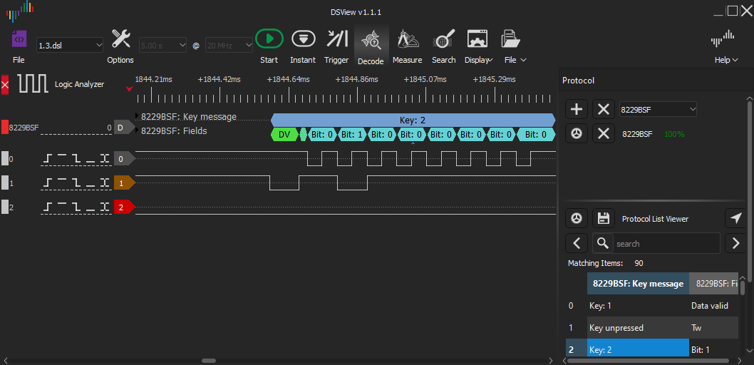
Until that moment, all the code worked only with the first package. Have you already noticed the 19% next to the decoder name? This is the percentage of samples that were processed before exiting the decode () function. To process all samples, it remains to add an endless loop around the code for decoding a separate data send ( 48f95fb ).
    def decode(self):
        ...
        while True:
            self.wait({Pin.SCL: self.passive_signal, Pin.SDO: self.front_edge})
            self.dv_block_ss = self.samplenum
            ...
Since decoding will automatically end if the wait () function iterates over all of them when searching for the next sample. As a result of this change, all samples and all data transmissions will be processed as shown in the KDPV .
The final touch remains to add the ability to select the active signal level and a full-fledged decoder for TTP229-BSF will be ready. The source code for the final version is also available on GitHub .