How it all began
Somehow we were going together with a brother and his friend together to go to Pripyat to go illegally, it was an old dream that was waiting for its realization, but never came to (But more on that later). When we had already prepared almost everything we needed, it turned out that no one had at least a simple radiation indicator. Having looked at the announcement site, I found little, everything was mostly either very far, or very expensive, and the idea came up to try to make my own from what was at hand, and all I had was an arduinka, counter (STS-5 ) and a lot of loose powder. So, as everything had to be done within a month, I began to look for ready-made projects so as not to reinvent the wheel, and I found the simplest project on the amateur radio site. The main problem was the winding of the transformer, in fact, which is why I abandoned this business.We did not go to Pripyat because the political situation worsened.
Resuming an old project
3 years have passed since the first attempt, I gained new knowledge, both in electrical engineering and in programming. I was eager to apply my knowledge and finally finish what I had begun, which I decided to do during self-isolation. I decided to start with the simplest thing, I ordered a boosting module, an arduino from China and looked in the bins in the hope of finding the right parts for the emitter repeater (For removing pulses). The first firmware simply counted the pulses from the interruption foot, and I was quite pleased even with such a not significant result, and this gave me a huge impetus in further improving the project.
Development start
Initially, it suited me that the boost converter would be a separate part of the device, but in the end the device would turn out to be huge, which I didn't really like. I began to sort out the options for the step-up circuit, and settled on a DC-DC with control, and feedback from a microcontroller. In fact, there was nothing difficult about this, but it was after adding your own converter that the problems began.
Houston, we have interference
As you can see from the title, there are terrible power interferences and more. When the voltage approached 400 volts, a complete bacchanalia began on the interruption leg. The interrupt was constantly working, and I simply could not understand for a long time what the problem was. Changing the frequency of the PWM did not help, power capacitors, too. I was already beginning to despair, but the decision came suddenly when I brought my finger to the leg of the interrupt. The device immediately began to function normally until the moment when I removed my finger. And then I remembered the behest of my old friend: "Put ceramics everywhere." After I set the ceramic capacitor to 100nF between the interrupt and ground, the problem is gone. It took me a lot of time to deal with this problem, but I will remember this lesson for a long time. As a result, I put the ceramic capacitors everywhere,wherever possible, and everything worked as it should.
Board development
I developed the board in the EasyEda editor, because I immediately decided to order boards from China. To be honest, the editor is convenient and intuitive. For me, the person who always made boards in SprintLayout, this program was just something beyond fantasy.
Now to the point. I wanted to make the device as small as possible, and chose a size of 50x100 mm, which is somewhat too much and could fit in a smaller size. I decided to make the first options on seven-segment indicators, which was a huge mistake, since they were extremely not informative, and it was quite difficult to display on them what I wanted. Next on my list was the display from the nokia 5110. This option more than satisfied me.
Its main advantages are:
- Does not require backlighting during the day.
- Low power consumption.
- Easy to use.
But there were also problems. The display requires 3.3 volts of power, and preferably 3.3 volts logic, and the microcontroller runs from 5 volts. The problem was solved with 10 kΩ resistors and a linear regulator.
The core of the device is the atmega328p-mu microcontroller. I chose precisely because, judging by the datasheet, it is more tenacious.
The device is autonomous and runs on a li-ion battery, therefore, the tp4056 chip and a low-power 5-volt dc-dc boost converter on the me2108a50 chip were divorced on the board.
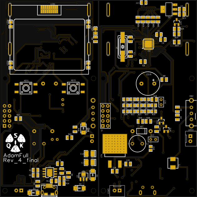
As a result, the board took the following form:
Why do you need it if you can buy it?
The device was developed as universal, so that you can change the sensor at any time and fine tune it.
The following characteristics for editing were rendered programmatically:
The settings of these characteristics allow you to connect any sensor, the operating voltage of which is not more than 800 volts (In order to increase the voltage, modifications are required), the counting time is not more than 100 seconds and the error is less than 50%.
The cost of the device goes 500 rubles. if you order parts from China and about 1000 rubles if you buy them in local radio parts. Of course, I did not take into account the cost of the counting tube. its price at flea markets usually does not exceed 500 rubles.
If you compare with devices that are close in characteristics, then 1000 rubles is a pretty appetizing price for fans to solder.
The assembled board looks like this:
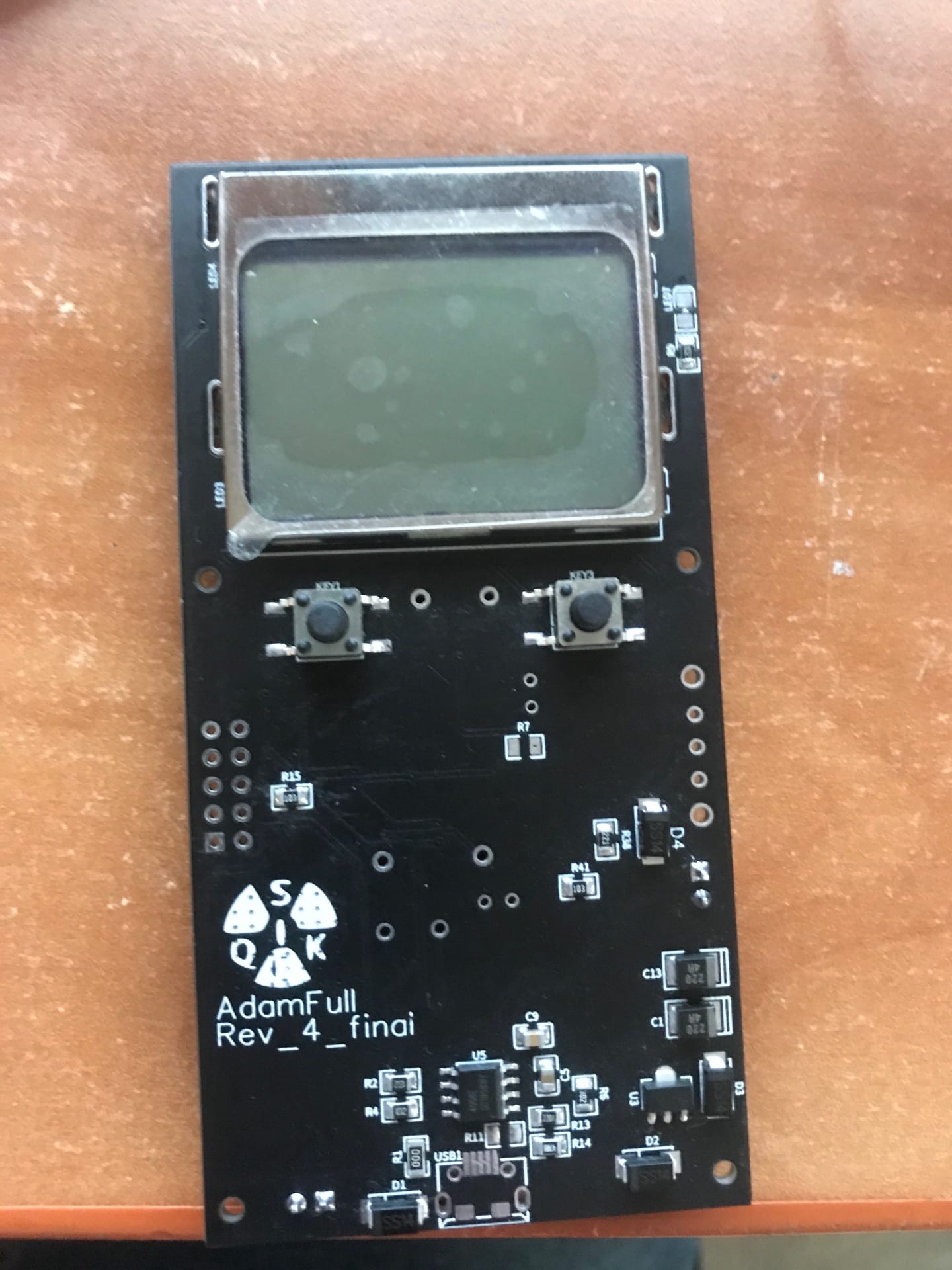
As you can see from the photo, the board is not yet fully assembled, since I did not find some components in my city and I need to wait for them from China.
To summarize
The development of a complete device is a rather time-consuming process that requires a lot of knowledge in low-level programming, instrument making and electrical engineering. It is very disappointing when the work invested in the development turns into the fact that the device is buggy and behaves differently from the layout. To be honest, the black version of the boards is the fourth version, before that there were variants with an unsuccessful choice of power supply scheme, an unsuccessful display and a lack of capacitors. This article is intended for those who want to assemble a similar device for themselves, or want to do something similar. Demonstration of the device will be in the next part of the article.
I hope I helped you and my project interested you. I am attaching links to the firmware repository and the PCB project:
github.com/AdamFull/Dosimeter-SQUICK
easyeda.com/AdamFull/geigercounter_nokia