
Ave Coder!
You got a cool product idea, but you don't want to get bogged down in the code and lose the whole picture due to small details? Are you about to sit down for the quack of a corporate server and you need to stuff something cool and IT?
This series of articles will be devoted to a useful, but sometimes elusive knowledge of the young growth - UML diagrams. And I'll start it with an overview of existing diagrams, let's talk a little about history and why there should be so many diagrams.
UML is short for Unified Modeling Language, and as we know, it is a standardized modeling language consisting of an integrated set of diagrams designed to assist system and software developers in identifying, visualizing, constructing, and documenting artifacts of software systems, as well as , for example, for business modeling.
The UML is a set of best engineering practices that have proven to be effective in modeling large and complex systems and is a very important part of object-oriented software development.
UML mainly uses graphical notation to express the design of software projects. Using the UML helps design teams communicate, explore potential projects, and validate the architectural design of software.
The origin of the UML
The goal of UML is to provide a standard notation that can be used by all object-oriented methods, as well as select and integrate the best elements of predecessor notations. The UML has been designed for a wide variety of applications. Consequently, it provides designs for a wide range of systems and activities (for example, distributed systems, analysis, design and deployment of systems).
The UML did not emerge from scratch, it was preceded by several significant events, personalities and methodologies. For example:
- OMT [James Rumbaugh 1991], .
- Booch [Grady Booch 1994] — . - . , , , , .
- OOSE (- [Ivar Jacobson 1992]) — , — , , .
In 1994, Jim Rambo was not to be confused with John Rambo, although Jim was also cool because he was, for a moment, the creator of the above object modeling technique, stunned the software world when he left General Electric and joined Grady Butch in Rational Corp. The goal of the partnership was to combine their ideas into a single unified method (the working name for the method was indeed "Unified Method").
By 1995, the creator of OOSE, Ivar Jacobson, had also joined Rational, and his ideas (in particular the concept of "use cases") were incorporated into a new unified method, now called the Unified Modeling Language.
In contrast to the well-known Gang of Four, Team Rumbo, Buch and Jacobson is known as the Three Amigos.
UML has also been influenced by other object-oriented notations:
- Mellor and Schlaer [1998]
- Coad and Yourdon [1995]
- Wirfs Brock [1990]
- Martin and Odell [1992]
UML also includes new concepts, which at that time were not in other basic methods, such as extension mechanisms and language constraints.
Why UML?
As the strategic value of software increased for many companies, the industry looked for methods to automate the production of software, as well as to improve quality and reduce costs and time to market.
These methods include component technology, visual programming, patterns, and structures.
Companies are also looking for methods to manage the complexity of systems as they scale up.
In particular, they recognize the need to address recurring architectural problems such as physical distribution, concurrency, replication, security, load balancing, and fault tolerance.
In addition, web development, while simplifying things, generally aggravates these architectural problems.
The Unified Modeling Language (UML) was developed to meet these needs.
The main goals of UML design are:
- Provide users with a ready-made, expressive visual modeling language so they can develop and share meaningful models.
- Provide extensibility and specialization mechanisms to expand core concepts.
- Be independent of specific programming languages and development processes.
- Provide a formal framework for understanding the modeling language.
- Encourage the growth of the market for object-oriented tools.
- Support for high-level design concepts such as collaboration, structures, templates, and components.
- Integrate best practices.
UML diagrams are classified into two types - structure diagrams and behavior diagrams.

Structural diagrams show the static structure of a system and its parts at different levels of abstraction and implementation, as well as their relationship. Elements in the structural diagram represent meaningful concepts of the system and may include abstract, real concepts and implementation concepts. There are seven types of structural diagrams:
- Composite structure diagram
- Deployment diagram
- Package diagram
- Profile Chart
- Class diagram
- Object diagram
- Component diagram
Behavior diagrams show the dynamic behavior of objects in a system, which can be described as a series of changes in the system over time. And the behavior diagrams include:
- Activity diagram
- Use case diagram
- State diagram
- Sequence diagram
- Communication diagram
- Interaction Overview Chart
- Timing chart
Now a few words about each of them
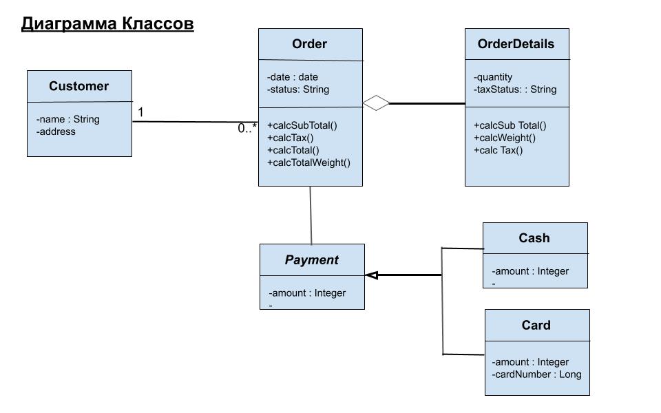
Class diagram
The class diagram is a central modeling technique that is used in almost all object-oriented methods. This diagram describes the types of objects in the system and the different kinds of static relationships that exist between them.
The three most important types of relationships in class diagrams (actually there are more) are: An
association that represents relationships between type instances, for example, a person works for a company, the company has several offices.
Inheritance, which closely matches inheritance in Object Oriented Design.
Aggregation, which is a form of composition of objects in an object-oriented design.
Component diagram
In unified modeling language, a component diagram shows how components come together to form larger components or software systems.
It illustrates the architectures of software components and the dependencies between them.
These software components include runtime components, executable components, and source code components.

Deployment diagram
A deployment diagram helps simulate the physical aspect of an object-oriented software system. This is a block diagram that shows the architecture of the system as the deployment (distribution) of software artifacts.
Artifacts represent specific elements in the physical world that are the result of the development process.
The diagram simulates the run-time configuration in a static view and visualizes the distribution of artifacts in the application.
In most cases, this includes modeling hardware configurations along with the software components on which they are located.

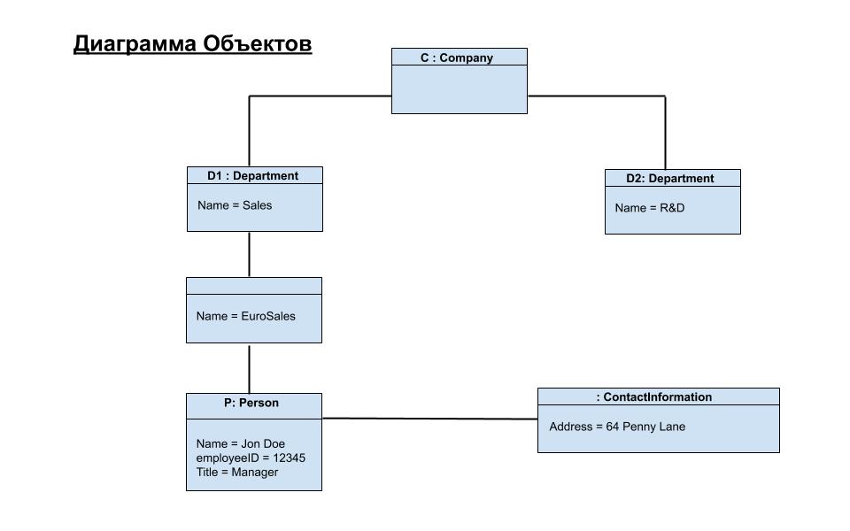
Object diagram
A static object diagram is an instance of a class diagram; it shows a snapshot of the detailed state of the system at a particular point in time. The difference is that a class diagram is an abstract model of classes and their relationships.
However, an object diagram is an instance at a particular moment that is of a specific nature. The use of object diagrams is rather limited, namely to show examples of data structure.
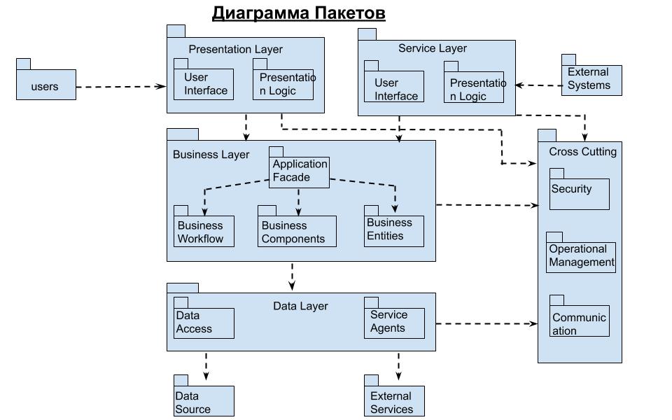
Package diagram
A package diagram is a UML structural diagram that shows packages and the dependencies between them.
It allows you to display different views of the system, for example, it is easy to model a multi-tier application.
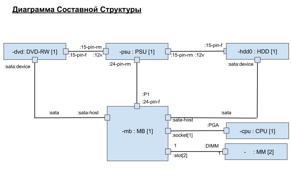
Composite structure diagram
Composite structure diagram is similar to class diagram and is a kind of component diagram used mainly in micro-level system modeling, but it depicts individual parts instead of entire classes. This is a type of static structural diagram that shows the internal structure of a class and the interactions that this structure makes possible.
This diagram can include internals, ports through which parts communicate with each other or through which class instances interact with parts and with the outside world, and connectors between parts or ports. A composite structure is a set of interconnected elements that interact at run time to achieve a goal. Each element has a role in collaboration.
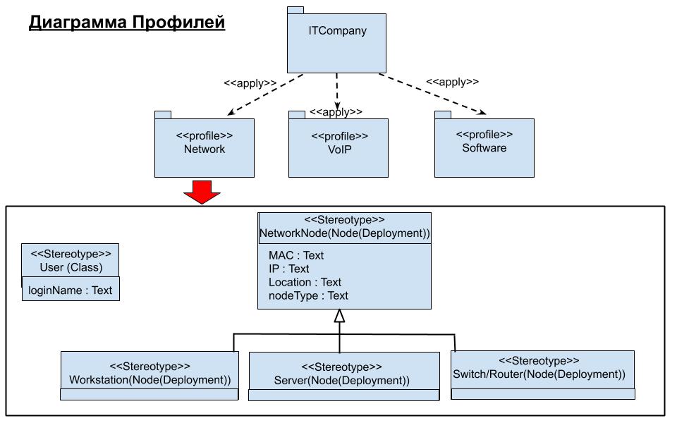
Profile Chart
The profile diagram allows us to create domain-specific and platform-specific stereotypes and determine the relationship between them. We can create stereotypes by drawing shapes of stereotypes and linking them to composition or generalization through a resource oriented interface. We can also define and visualize the meaning of stereotypes.
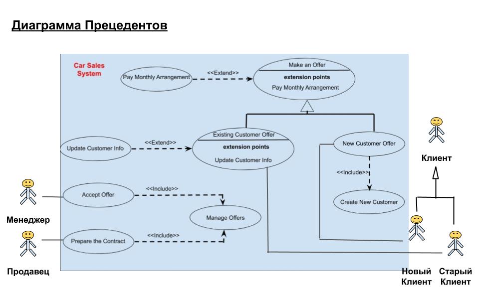
Use case diagram
A use case diagram describes the functional requirements of a system in terms of use cases. In essence, this is a model of the supposed functionality of the system (precedents) and its environment (actors).
Precedents allow us to connect what we need from the system with how the system satisfies these needs.
Activity diagram
Activity diagrams are graphical representations of step-by-step and step-by-step workflows with support for selection, iteration, and concurrency.
They describe the control flow of the target system, such as the study of complex business rules and operations, as well as the use cases and business processes.
In UML, activity diagrams are designed to simulate both computational and organizational processes.

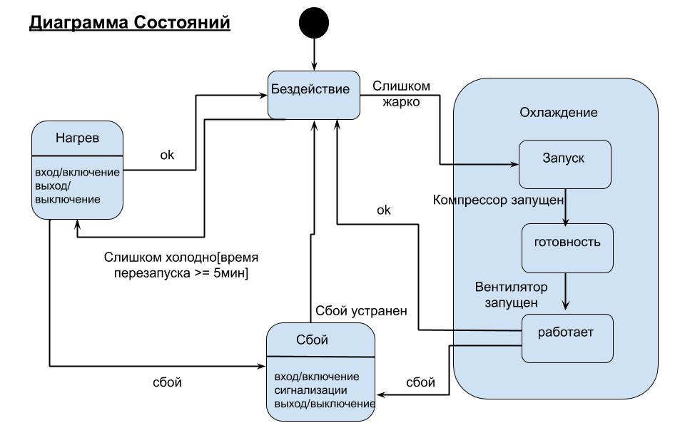
State diagram
A state diagram is a type of diagram used in UML to describe the behavior of systems, which is based on David Harel's concept of state diagrams. State diagrams show the enabled states and transitions, and the events that affect those transitions. It helps to visualize the entire life cycle of objects and, thus, helps to better understand state-based systems.
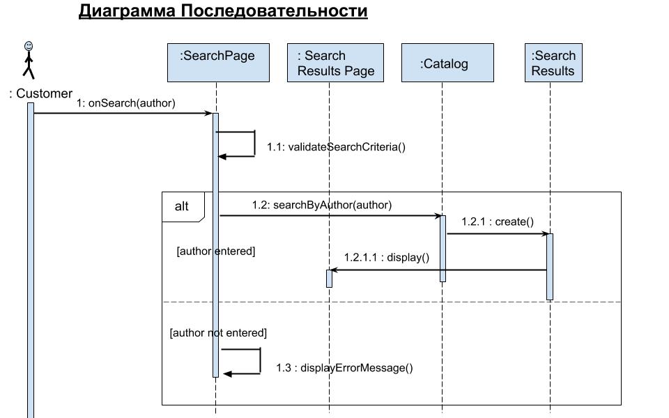
Sequence diagram
A sequence diagram models the interaction of objects based on a time sequence. It shows how some objects interact with others in a specific use case.
Communication Diagram
Like a sequence diagram, a communication diagram is also used to model the dynamic behavior of a use case. Compared to the sequence diagram, the communication diagram is more focused on showing the interaction of objects, rather than the time sequence. In fact, communication diagram and sequence diagram are semantically equivalent and can flow into one another.

Interaction Overview Chart
The interaction overview diagram focuses on an overview of the interaction management flow. This is a variant of the Activity Diagram where the nodes are interactions or interaction events. An interaction overview diagram describes interactions in which messages and lifelines are hidden. We can link “real” diagrams and achieve a high degree of navigation between diagrams within an interaction overview diagram.

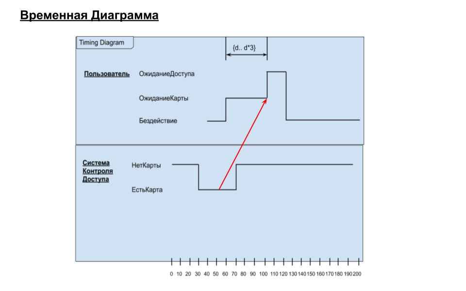
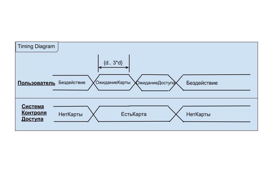
Timing chart
The timing diagram shows the behavior of the object (s) at a given time period. In fact, this is a special form of a sequence diagram and the differences between them are that the axes are swapped so that time increases from left to right, and the life lines are displayed in separate compartments located vertically.
Why are there so many diagrams in UML?
The reason for this is that you can look at the system from different points of view, because many interested parties will participate in software development, such as: analysts, designers, coders, testers, quality control, customers, technical authors.

All these people are interested in various aspects of the system, and each of them requires a different level of detail.
For example, the encoder must understand the design of the system and be able to convert the design into low-level code.
On the contrary, a technical writer is interested in the behavior of the system as a whole and must understand how the product functions.
UML is trying to provide the language in such an expressive way that all interested parties can benefit from at least one UML diagram.
For those who are too lazy to read:
Ave!