Formulation of the problem
You were persuaded to design a refreshment machine for the office. The cost of drinks is partially covered by the union, so they cost only 5 rubles. The machine accepts coins of 1, 2 and 5 rubles. As soon as the customer pays in the required amount, the machine will dispense the drink and return the change. Design a state machine for a soft drink vending machine. The inputs of the machine are 1, 2 and 5 rubles, namely, which of these coins is inserted.
Suppose only one coin is inserted per clock. The machine has outputs: pour soda, return 1 ruble, return 2 rubles, return 2 to 2 rubles. As soon as 5 rubles (or more) is collected in the machine, it sets the signal “Pour GASING”, as well as signals returning the corresponding change. The machine must then be ready to accept coins again.
Theory
Finite state machines or finite state machines (FSMs) belong to the class of synchronous sequential circuits that represent the vast majority of digital circuitry. This is how you should implement your projects (at least at first). This method provides repeatability and verification of the circuit and does not depend on the delay ratios of various circuit elements. The rules for constructing synchronous sequential circuits state that a circuit is a synchronous sequential circuit if its elements satisfy the following conditions:
- Each element of the circuit is either a register or a combinational circuit.
- At least one schema element is a register.
- All registers are clocked with a single clock signal.
- Each cyclic path contains at least one register.
A state machine has several states, which it stores in registers. When a clock signal arrives, the state machine can change its state, and how exactly the state changes depends on the input signals and the current state. In the simplest case, there may not be any input signals at all, thus the frequency divider works. There are two main classes of finite state machines: the Moore automaton, in which the output signals depend only on the current state of the automaton, and the Mealy automaton, in which the output signals depend on the current state and input signals. In principle, any finite state machine can be implemented both according to the Moore scheme and the Miley scheme, the difference between them will be that the Moore automaton will have more states and it will be one clock behind the Mily automaton.For the soda machine circuit, I will use the Miles circuit. Let us state the state machine:
| Symbol | Description |
|---|---|
| S 0 | The initial state, the accumulated amount of 0 rubles. |
| S 1 | The accumulated amount is 1 rub. |
| S 2 | Accumulated 2 rubles. |
| S 3 | Accumulated 3 rubles. |
| S 4 | Accumulated 4 rubles. |
The input signal will be a two-bit bus, with the following coding of the coin denomination:
| Symbol | Value | Description |
|---|---|---|
| I 1 | 01 | 1 rub |
| I 2 | ten | RUB 2 |
| I 5 | eleven | 5 rub |
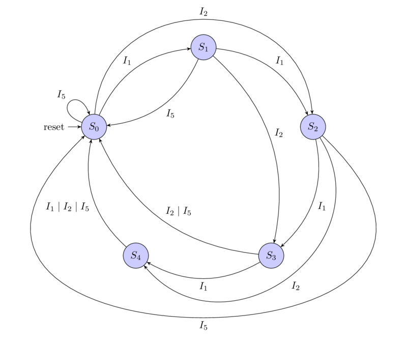
We will draw a state diagram of our automaton (on the state diagrams of the Mily automaton, it is necessary to indicate the output signals on the arrows of the state transition, I will not do this so as not to clutter up the diagram, all output signals will be painted in the table below):
We will write a table of changes in states and output signals:
| States | Input signals | |||||
|---|---|---|---|---|---|---|
| S | S' | insert | pour_water | C 1 . change1 | 2 . change2 | 2 2 . change22 |
| S0 | S1 | I1 | 0 | 0 | 0 | 0 |
| S0 | S2 | I2 | 0 | 0 | 0 | 0 |
| S0 | S0 | I5 | 1 | 0 | 0 | 0 |
| S1 | S2 | I1 | 0 | 0 | 0 | 0 |
| S1 | S3 | I2 | 0 | 0 | 0 | 0 |
| S1 | S0 | I5 | 1 | 1 | 0 | 0 |
| S2 | S3 | I1 | 0 | 0 | 0 | 0 |
| S2 | S4 | I2 | 0 | 0 | 0 | 0 |
| S2 | S0 | I5 | 1 | 0 | 1 | 0 |
| S3 | S4 | I1 | 0 | 0 | 0 | 0 |
| S3 | S0 | I2 | 1 | 0 | 0 | 0 |
| S3 | S0 | I5 | 1 | 1 | 1 | 0 |
| S4 | S0 | I1 | 1 | 0 | 0 | 0 |
| S4 | S0 | I2 | 1 | 1 | 0 | 0 |
| S4 | S0 | I5 | 1 | 0 | 0 | 1 |
Quartus Prime
Quartus has a free Lite Edition, which has some limitations compared to the professional edition, the main limitation is no more than 10,000 lines of source code for simulating a project. Download it, after registration, you can follow the link , at the time of writing the latest version was 19.1, based on working with this version, I wrote an article. We select Lite Edition, version 19.1, the Windows operating system (it should be noted that there is a Quartus version for Linux and it works fine, problems arise with ModelSim, which is 32 bit and uses the old version of the font mapping library, so at first I recommend using the Windows version ), select the Combined Files tab. The size of the archive for the download is quite large - 5.6 Gb, keep this in mind. Expand the downloaded archive and runsetup.bat . Installation takes place in a standard way, we use the default selection of components.
Project creation
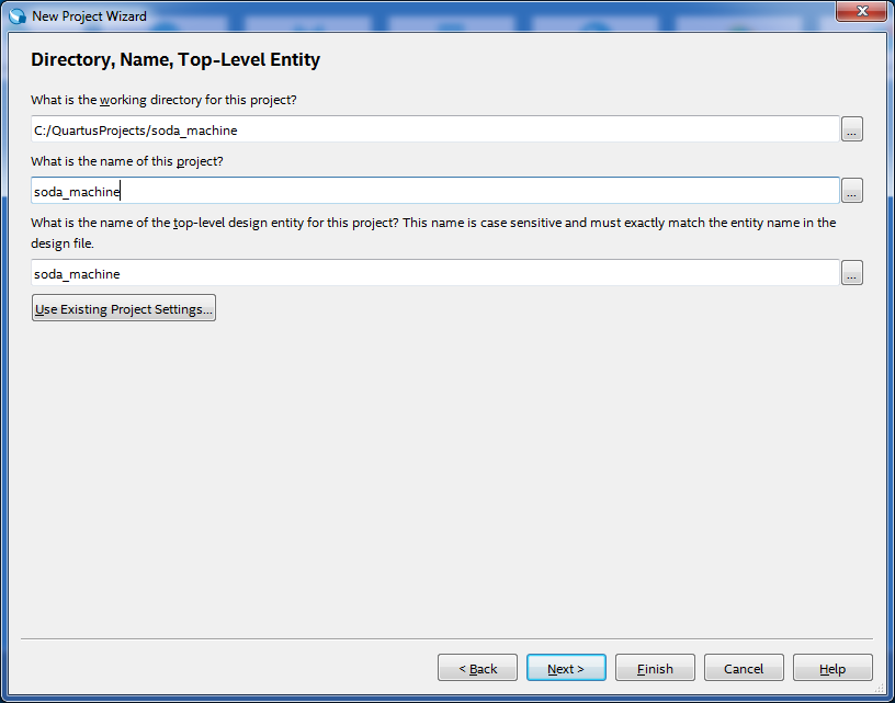
To create a new project, select the File -> the New ... by Project Wizard . The first Wizard window is informational, click Next , on the second window we select where the project will be located, its name is “soda_machine” and the top-level design element is “soda_machine” , as in the figure:
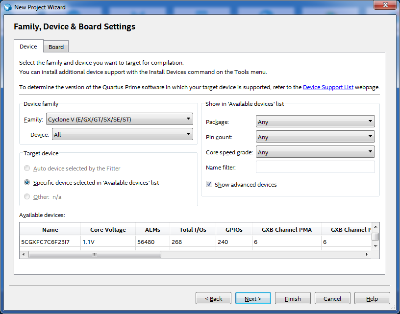
In the next window, select “Empty project” . The window for adding files "Add files" , do not add anything. The window for selecting the “Family, Devices & Board Settings” device is very important for a real project, but since our project is far from real, we leave the default settings here, as in the figure:
Window for selecting settings for other tools“EDA Tool Settings” , we choose to use “ModelSim-Altera” and the format “System Verilog HDL” to simulate the project as in the figure:

Last information window “Summary” , click Finish .
Writing source code
We will have two main files with the source code, this is the soda_machine module itself and its test bench, both of these files will use the insert_type data type , which describes how we encode coin values and it is logical to separate it into a separate file. But there are some difficulties associated with the compilation features of Quartus and ModelSim. Quartus compiles all the source files in a single pass, and ModelSim compiles each file separately for that would compile Quartus'om arose override type insert_type , I used the technique of the C / C ++ include guard, based on the directives of the macro processor. In addition, for ModelSim to be sure that the insert_type used in the soda_machine moduleand in the test bench, the same one, placed its description inside the soda_machine_types package . Given these requirements, the soda_machine_types.sv file is as follows:
soda_machine_types.sv
`ifndef soda_machine_types_sv_quard

package soda_machine_types;

	typedef enum logic [1:0] {I1=2'b01, I2=2'b10, I5=2'b11} insert_type;

endpackage

`define soda_machine_types_sv_quard
`endif
Now the soda_machine module itself is located in the soda_machine.sv file :
soda_machine.sv
`include "soda_machine_types.sv"
import soda_machine_types::*;


module soda_machine(
	input logic clk,          // Clock
	input logic reset,        // Active high level
	input insert_type insert,
	output logic pour_water,
	output logic change1,
	output logic change2,
	output logic change22);

	typedef enum logic [2:0] {S0, S1, S2, S3, S4} state_type;
	(* syn_encoding = "default" *) state_type state, nextstate;
	//
	always_ff @(posedge clk, posedge reset)
	if (reset)
		state <= S0;
	else
		state <= nextstate;
	//
	always_comb
		case (state)
			S0:
				case (insert)
					I1:
						nextstate = S1;
					I2:
						nextstate = S2;
					I5:
						nextstate = S0;
				endcase
			S1:
				case (insert)
					I1:
						nextstate = S2;
					I2:
						nextstate = S3;
					I5:
						nextstate = S0;
				endcase
			S2:
				case (insert)
					I1:
						nextstate = S3;
					I2:
						nextstate = S4;
					I5:
						nextstate = S0;
				endcase
			S3:
				if (insert == I1)
					nextstate = S4;
				else
					nextstate = S0;
			S4:
				nextstate = S0;
		endcase
	//
	assign pour_water = (state == S4) | (insert == I5) | (state == S3) & (insert == I2);

	assign change1 = (state == S1) & (insert == I5) | (state == S3) & (insert == I5) | (state == S4) & (insert == I2);

	assign change2 = (state == S2) & (insert == I5) | (state == S3) & (insert == I5);

	assign change22 = (state == S4) & (insert == I5);

endmodule
How the state of the state machine will be encoded, I left it up to Quartus. In order to indicate how exactly the encoding should be performed, the attribute (* syn_encoding = "default" *) is used , other encoding options can be seen here .
It should be noted that in a real project, the output signals of the combinational logic of the Miles machine must be stored in registers and fed from the output of the registers to the FPGA output. Input signals must be synchronized with the clock frequency using synchronizers in order to avoid falling into a metastable state.
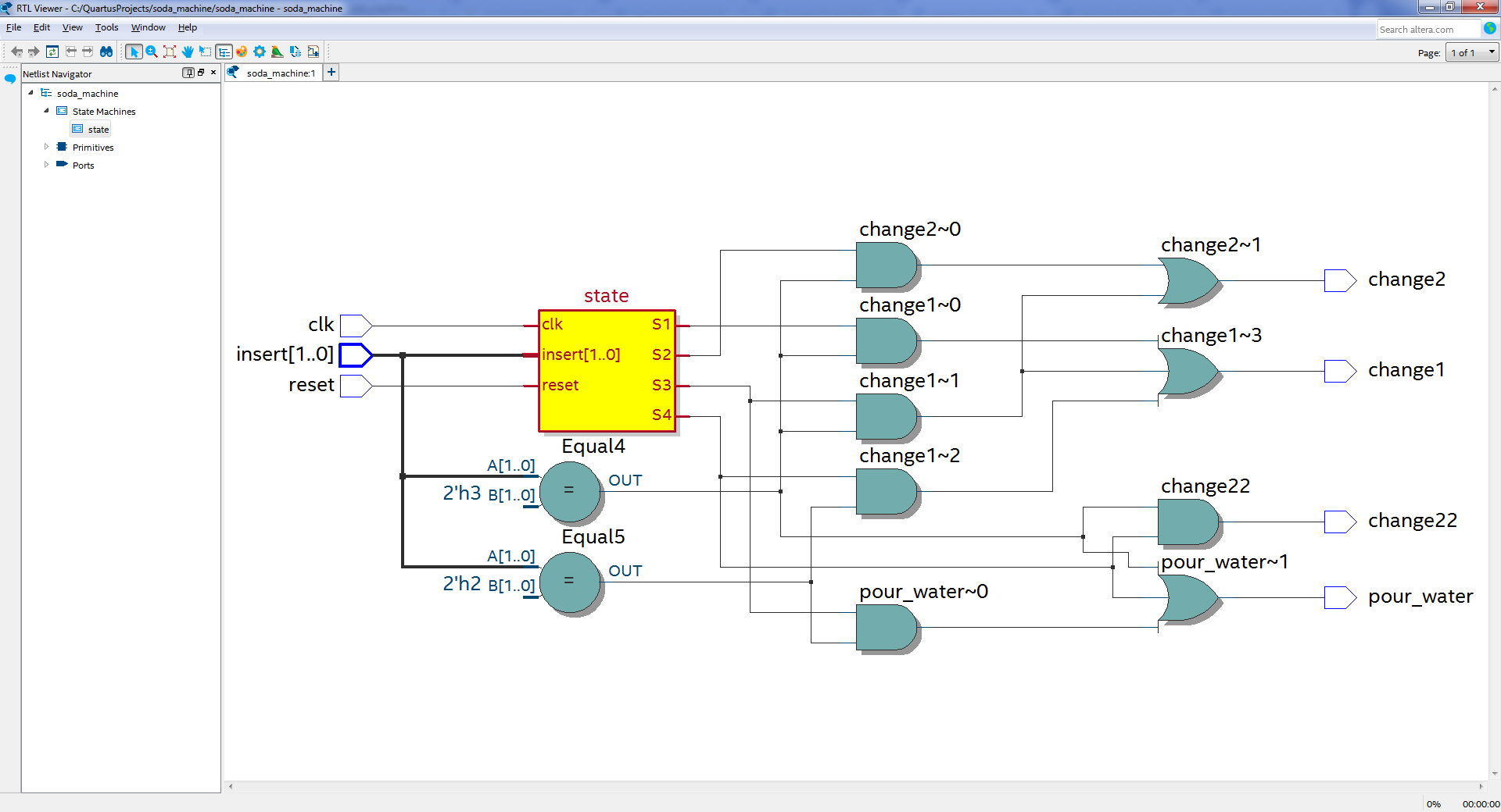
To add files to the project, use File -> New "SystemVerilog HDL File"and when saving give the appropriate name. After adding these two files, the project can be compiled with Processing -> Start Compilation . After successful compilation, you can see the resulting scheme Tools -> Netlist Viewers -> RTL Viewer :
RTL Viewer
To view the state machine statechart Tools -> Netlist Viewers -> State Machine Viewer
State Machine Viewer

On the Encoding tab, you can see that Quartus applied the “one-hot” encoding scheme, this is when a separate D-trigger is used for each state, and the state S 0 is encoded 0, not 1 as for other states, this is done to simplify the initial reset scheme state. You may notice that the RTL Viewer does not show a very basic diagram, it is rather a concept. To view the schematic diagram use Tools -> Netlist Viewrs -> Technology Map Viewer (Post-Fitting)
Simulation
In principle, at the moment we have a diagram of a vending machine for selling soda water, but we need to make sure that it works correctly, for this we will write a test bench and place it in the soda_machine_tb.sv file :
soda_machine_tb.sv
`include "soda_machine_types.sv"
import soda_machine_types::*;

module soda_machine_tb;

	insert_type insert;

	logic [5:0] testvectors[10000:0];

	int vectornum, errors;

	logic clk, reset, pour_water, change1, change2, change22;
	logic pour_water_expected, change1_expected, change2_expected, change22_expected;
	//
	soda_machine dut(
		.clk(clk),
		.reset(reset),
		.insert(insert),
		.pour_water(pour_water),
		.change1(change1),
		.change2(change2),
		.change22(change22)
	);
	//
	always
		#5 clk = ~clk;
	//
	initial begin
		//
		$readmemb("../../soda_machine.tv", testvectors);
		vectornum = 0;
		errors = 0;
		clk = 1;
		//
		reset = 1; #13; reset = 0;
	end
	//
	always @(posedge clk) begin
		#1; {insert, pour_water_expected, change1_expected, change2_expected, change22_expected} = testvectors[vectornum];
	end
	// ,
	always @(negedge clk)
		if (~reset) begin
			if ((pour_water !== pour_water_expected) || (change1 !== change1_expected) || (change2 !== change2_expected) ||
				(change22 !== change22_expected)) begin
				$error("%3d test insert=%b\noutputs pour_water=%b (%b expected), change1=%b (%b expected), change2=%b (%b expected), change22=%b (%b expected)",
					vectornum + 1, insert, pour_water, pour_water_expected, change1, change1_expected, change2, change2_expected, change22, change22_expected);
				errors = errors + 1;
			end
			vectornum = vectornum + 1;
			if (testvectors[vectornum] === 6'bx) begin
				$display("Result: %3d tests completed with %3d errors", vectornum, errors);
				$stop;
			end
		end

endmodule
To test our module, we use the soda_machine.tv test vector file :
soda_machine.tv
01_0_0_0_0
01_0_0_0_0
01_0_0_0_0
01_0_0_0_0
01_1_0_0_0
10_0_0_0_0
10_0_0_0_0
10_1_1_0_0
11_1_0_0_0
10_0_0_0_0
10_0_0_0_0
11_1_0_0_1
10_0_0_0_0
11_1_0_1_0
01_0_0_0_0
01_0_0_0_0
01_0_0_0_0
11_1_1_1_0
The first two bits are the insert input, the next 4 bits are our wait for the outputs: pour_water, change1, change2, change22. For example, at the beginning of the file, a ruble coin is inserted 5 times in a row, on the fifth coin, we wait for the pour_water signal to appear, while the change signals are inactive. The soda_machine.tv file is added to the File -> New “Text File” project.
For the convenience of working with ModelSim, add the soda_machine_run_simulation.do file with the following contents:
soda_machine_run_simulation.do
add wave /soda_machine_tb/dut/clk
add wave /soda_machine_tb/dut/reset
add wave /soda_machine_tb/dut/insert
add wave /soda_machine_tb/dut/state
add wave /soda_machine_tb/dut/nextstate
add wave /soda_machine_tb/dut/pour_water
add wave /soda_machine_tb/dut/change1
add wave /soda_machine_tb/dut/change2
add wave /soda_machine_tb/dut/change22
view structure
view signals
run -all
wave zoom full
It will run our simulation and display the waveforms in ModelSim. The soda_machine_run_simulation.do file is added to the project File -> New "Tcl script File"
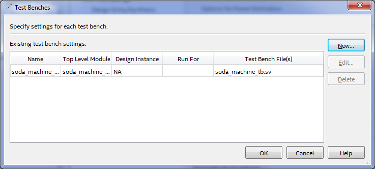
Now we will set up the project so that the simulation starts automatically. Select the menu item Assignments -> Settings , select the category EDA Tool Settings -> Simulation . In the NativeLink settings, select Compile test bench: and click the Test Benches button ... in the Test Benches window that opens, click the New button ... In the New Test Bench Settings window that opens, fill in the Test bench name: soda_machine_tb fieldand click the file selection button ... at the bottom of the window, select our soda_machine_tb.sv file and click the Add button . It should turn out as in the figure:

In the New Test Bench Settings window, click OK . The Test Benches window should look like this:
In the Test Benches window, click OK . In NativeLink settings , select the Use script to set up simulation checkbox and select the soda_machine_run_simulation.do file . The Settings window
should look like this:

In the Settings window, clickOK , we compile the project Processing -> Start Compilation , run the simulation Tools -> Run Simulation Tool -> RTL Simulation . ModelSim should start and the project will simulate. Transcript tab appearance:
ModelSim Transcript Tab
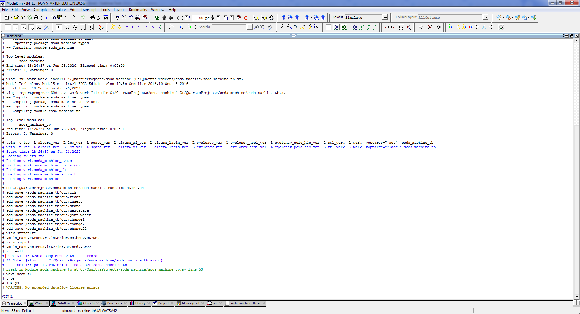
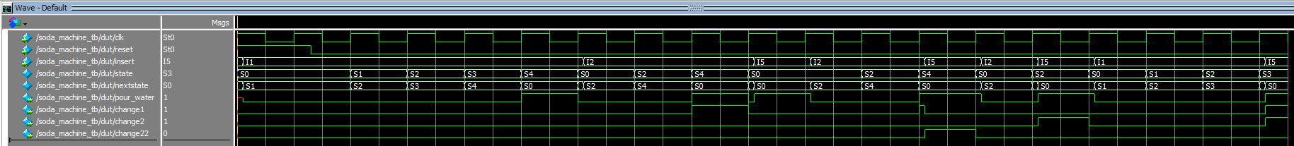
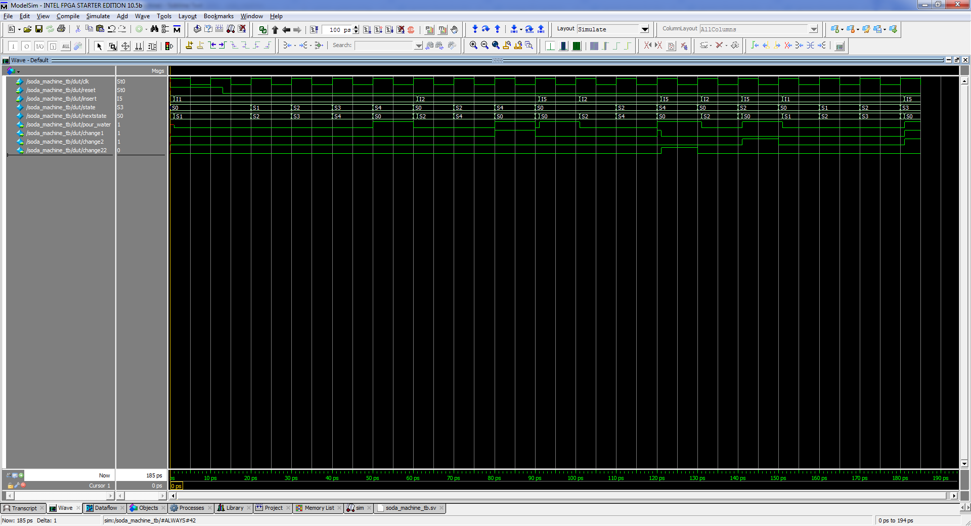
The red frame marks the output of our test bench about the number of tests performed and errors found. Wave tab appearance:
ModelSim Wave tab
Project source code
The source code for the project is at github.com/igoral5/soda_machine Clone the project, then open the project with Quartus File -> Open Project ...
select the soda_machine.qpf file . Then compile the project Processing -> Start Compilation and run the simulation Tools -> Run Simulation Tool -> RTL Simulation .